


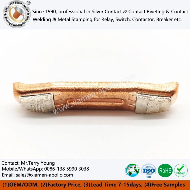


What are Brazing Silver Contacts to Copper Bars?
Silver contacts serve as the switching surface, while copper bars conduct current to the main circuit. Core process steps of Brazing Silver Contacts to Copper Bars include copper substrate preparation, silver‑contact positioning, regulated heating, flux treatment, controlled cooling, and post‑brazing finishing. This process fits high‑current switch assemblies, in which brazed joints must maintain stable electrical conductivity against mechanical stress and repeated thermal cycling. Compared with slim spring‑based relay contacts, copper‑bar units have higher thermal mass and unique heat transfer characteristics. Precise temperature control ensures filler metal fully wets the bonding interface and prevents overheating of both copper bars and silver contacts.
Two production modes are available: customer‑supplied material processing and full‑scope OEM manufacturing. Clients may provide copper bars, silver contacts, and technical drawings, or we can fabricate finished parts entirely according to official engineering requirements.

Technical Specifications & Materials
| Technical Parameter | Specification Value |
| Electrical Conductivity | > 85% IACS (Tip), > 100% IACS (Copper bar) |
| Shear Strength / Bonding Force | > 190 MPa |
| Contact Resistance | < 0.4 mΩ |
| Dimensional Tolerance | ±0.03 mm (Contact position) |

Joint Design Guidelines for Silver Contact Joining Assembly
Contact Footprint
The silver contact footprint should provide sufficient effective brazed area for the intended electrical and mechanical loading. The contact footprint should be dimensioned from the copper-bar datum rather than positioned by visual alignment.
Joint Clearance
The appropriate clearance depends on the selected filler metal, base-metal combination, brazing temperature, and joint geometry. A single generic clearance should not be applied to all Silver Contact Component Assemblies.
Copper-Bar Datum
Critical contact location should reference a stable copper-bar datum. This is particularly important where the Electrical Contact Tip Assembly will later be installed into a contactor, breaker, or other switching mechanism.
Thermal Relief
Large copper sections can conduct heat away from the brazing zone rapidly, while holes, bends, and changes in section can create local thermal differences for Brazed Electric Contacts. Fixture and heating design should therefore account for the complete bar geometry.

Typical End-Use Equipment & Working Conditions of Brazed Contact Components
Molded Case Circuit Breakers: MCCB Silver Contact Brazed Assemblies can be used in MCCB contact systems where the copper bar provides the current-carrying structure and the silver contact forms the switching interface.
Industrial Contactors: High-current contactors require conductive contact assemblies with controlled contact location and joint integrity. The copper-bar geometry is normally linked directly to the main-current path and mechanical assembly.
Power Distribution Assemblies: Copper Spot Welding Silver Contact can be integrated into power distribution equipment where current-carrying capacity, thermal behavior, and mechanical positioning must be considered together.
High-Current Switching Equipment: Compared with small relay contacts, Brazed Contact Components are designed around larger conductive sections and higher current paths. The brazing process must therefore consider copper heat absorption, joint area, contact position, and thermal cycling.

contact us
Send the Brazing Silver Contacts to Copper Bars drawing, silver contact specification, contact position, filler requirement, and expected production quantity for engineering review.
Brazing Electrical Contacts can be processed as supplied, or the complete assembly can be produced from material preparation through brazing, inspection, and final packaging. The production route can be defined around the actual product geometry, electrical requirements, and inspection criteria rather than applying a generic brazing process.

Hot Tags: Brazing Silver Contacts To Copper Bars, Brazed Contact Assembly, Silver Copper Bar Brazing, Electrical Contact Bonding, Low‑Voltage Switch Assembly, Circuit Breaker Silver Contact, Industrial Switch Contact Part, Power Distribution Contact, Induction Brazing Contacts, Resistance Brazing, OEM Electrical Contact Manufacturer, Custom Silver Contact Brazing, Heavy‑Duty Welded Contacts, Welding Electrical Contact Terminal, Silver Contact Brazing With Copper Plate And Brass Bolt, Elevator Switch Welded Silver Contacts, brazed contact assembly, Electrical Brazing Welded Silver Contacts Assembly, Electric Resistance Welding Silver Contact


