Aluminum stamping for solar mounting and CNC machining for inverter components address different manufacturing requirements: stamped parts support repeatable, high-volume production of brackets and mounting hardware, while CNC-machined parts provide controlled interfaces, threaded features, and dimensional accuracy for inverter assemblies. Alloy selection among 6061-T6, 6063, and 5052 must account for structural loading, corrosion exposure, forming behavior, thermal management, and the dimensional requirements of the finished component.
For solar equipment OEMs, the engineering objective is to specify the alloy, manufacturing route, surface treatment, and inspection method together. A low-cost blank can become an expensive production problem if stamping cracks, machining distortion, coating buildup, or incompatible fasteners compromise final assembly.

Aluminum Alloy Selection for Solar Mounting Metal Components
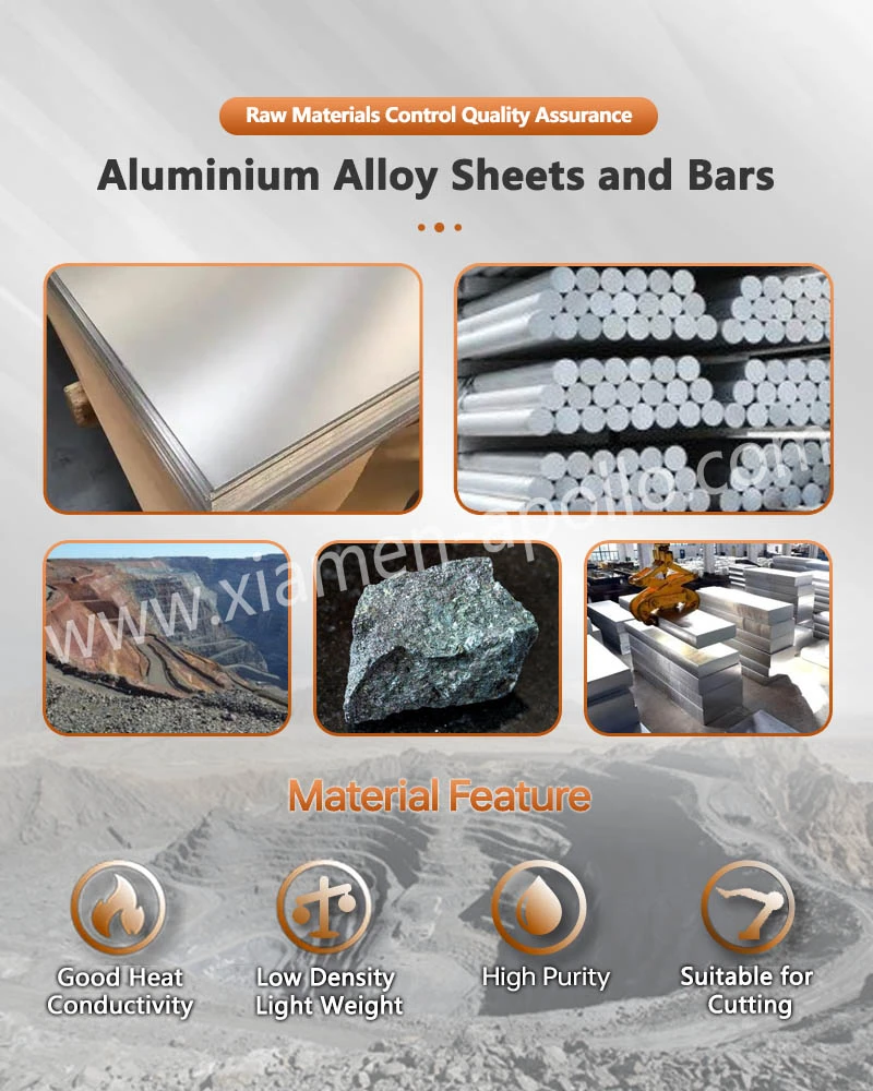
The correct aluminum grade depends on the component's load path, geometry, forming sequence and operating environment. The 6061-T6 alloy is frequently considered for machined structural interfaces; 6063 is widely used for extruded profiles; and 5052 is commonly selected for sheet-metal parts requiring good formability and corrosion resistance.
Comparing 6061-T6, 6063 and 5052 for Solar Equipment
| Property or manufacturing factor | 6061-T6 | 6063 | 5052 |
|---|---|---|---|
| Alloy family | Heat-treatable Al-Mg-Si | Heat-treatable Al-Mg-Si | Non-heat-treatable Al-Mg |
| Typical product forms | Plate, bar, extrusion | Extrusion, profile, bar | Sheet, plate, coil |
| Primary manufacturing fit | CNC-machined brackets, mounting blocks and interfaces | Extruded rails, channels and heat-sink profiles | Stamped covers, formed brackets and sheet-metal enclosures |
| Formability | Moderate; temper and bend radius matter | Good in suitable tempers and profile geometries | Good for many sheet-forming operations |
| Machinability | Generally good | Generally good, depending on temper and geometry | Generally workable; alloy condition affects cutting behavior |
| Corrosion behavior | Good atmospheric corrosion resistance with appropriate design and finish | Good atmospheric corrosion resistance | Good resistance in many outdoor and marine-adjacent environments |
| Strength considerations | T6 temper supports higher strength than common annealed conditions | Depends strongly on temper and extrusion geometry | Strength depends on temper; not precipitation-hardened |
| Design limitation | Tight bends may crack in T6 material; machining can expose residual stress | Thin-wall sections may distort during machining or clamping | Deep draws and tight bends require tooling and material-condition validation |
The table describes general engineering tendencies rather than guaranteed design values. Actual tensile strength, yield strength, elongation and hardness must be taken from the applicable alloy specification, temper, product form and material certificate.
When 6061-T6 Is Suitable for Aluminum CNC Inverter Parts
6061-T6 is a practical candidate for inverter mounting blocks, connector supports, machined end plates and interfaces that require tapped holes or controlled locating surfaces. Its mechanical properties support rigid interfaces without requiring a steel component in every application.
The design review should address:
- Thread engagement: Specify the required thread size, engagement length and allowable stripping load. Thin aluminum sections may need inserts or increased wall thickness.
- Wall thickness: Avoid abrupt transitions between thick bosses and thin walls where machining stress can cause distortion.
- Hole position: Define true position relative to the functional datum structure rather than assigning unnecessarily tight tolerances to every hole.
- Electrical isolation: Do not assume that an anodized surface provides a qualified insulation barrier unless coating thickness, continuity and dielectric requirements have been verified.
- Thermal interfaces: For heat-sink or power-module interfaces, control flatness and surface finish according to the thermal-interface material and clamping design.
For a machined part, a tolerance of ±0.05 mm may be a reasonable initial discussion point for selected non-critical features. A requirement such as ±0.01 mm should be reserved for features where the assembly design and measurement capability justify it. These are proposed design targets, not universal process guarantees.
When 5052 Is Better for Stamped Solar Mounting Components
5052 is often a suitable choice for stamped brackets, protective covers, cable-support plates and formed sheet-metal parts. Its formability can reduce cracking risk in bends and drawn features compared with less suitable high-strength tempers.
Before releasing a stamping drawing, define the following:
- Material grade and temper, such as the specified 5052-H32 condition.
- Sheet thickness and thickness tolerance.
- Grain direction relative to the principal bend lines.
- Minimum inside bend radius based on thickness, temper and forming direction.
- Burr direction, edge condition and permissible sharp edges.
- Flatness and hole-position requirements after forming.
- Surface-finish requirements for exposed or coated faces.
A nominal sheet thickness of 1.5 mm, for example, does not establish a universal minimum bend radius. The radius must be validated against the actual temper, grain direction, tooling and part geometry.
Why 6063 Extrusions Are Relevant to Solar Mounting Systems
6063 is frequently used for solar mounting rails, channels and heat-sink profiles because extrusion can produce long, repeatable cross-sections with integrated ribs and mounting slots. Where a mounting system combines extruded profiles with stamped brackets or CNC-machined adapters, the interface design determines the final assembly accuracy.
The engineering review should include profile straightness, twist, cross-sectional tolerance, fastener clearance and the effect of anodizing on slot dimensions. Extruded-profile tolerances should be specified using the applicable product standard and the supplier's demonstrated capability rather than copied directly from CNC machining tolerances.
High-Speed Aluminum Stamping: Tooling, Tolerances and Defect Control
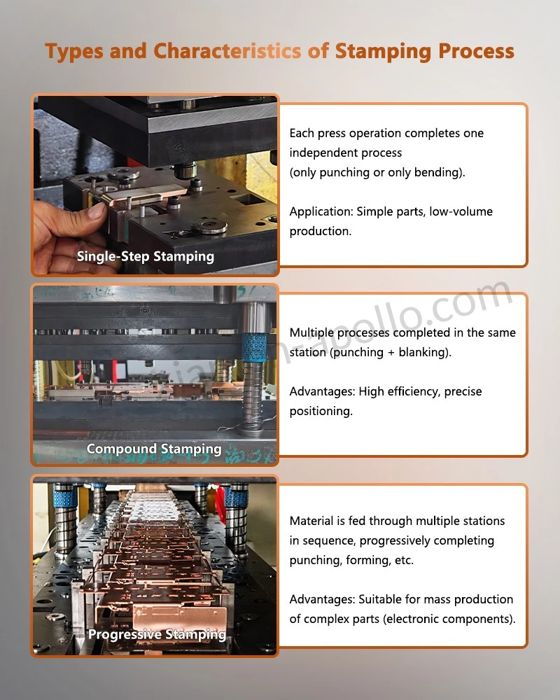
High-speed stamping can reduce unit cost for repeat-order solar mounting components when the part geometry, material condition and production volume justify dedicated tooling. The main controls are strip layout, burr formation, punch-to-die clearance, springback, die wear and dimensional variation across the production run.
Progressive Die Stamping for Repeated Mounting Features
Progressive die stamping performs successive operations as a metal strip advances through multiple stations. Depending on part geometry, these operations can include piercing, notching, embossing, bending and cutoff.
A production-ready stamping plan should define:
- Strip layout: Confirm material utilization, carrier stability and the relationship between grain direction and bend orientation.
- Die clearance: Establish clearance from the actual alloy, temper and sheet thickness; excessive or insufficient clearance can increase burrs, cutting load or edge deformation.
- Station sequence: Complete operations in an order that limits distortion and maintains stable part location.
- Pilot and feed control: Check strip pitch, feed alignment and pilot-hole wear to prevent cumulative positional errors.
- Tool wear monitoring: Track punch condition, burr height and dimensional trends at a defined sampling frequency.
- Part separation: Prevent nested parts, double feeds and scrap fragments from entering downstream assembly.
A stamping speed such as 100–300 strokes per minute may be feasible for some small, uncomplicated parts. It should not be treated as a general production commitment: actual speed depends on press capacity, strip thickness, station count, die construction, feed stability and inspection requirements.
Dimensional Tolerance and Burr Requirements for Aluminum Stamping
Stamped-part tolerance is influenced by material variation, die clearance, tool wear, springback and the measurement datum. A drawing that assigns ±0.05 mm to every feature may increase tooling and inspection costs without improving assembly performance.
| Feature | Suggested engineering control | Verification method |
|---|---|---|
| Pierced-hole diameter | Specify tolerance according to fastener fit and functional clearance | Pin gauges or calibrated optical measurement |
| Hole-to-edge distance | Define from a stable datum and account for edge variation | Optical comparator or coordinate measurement |
| Bend angle | Define the angle after springback, with a stated measurement condition | Angle gauge or CMM |
| Flatness after forming | Set according to mounting contact and assembly requirements | Surface plate and indicator or CMM |
| Burr height | Define a maximum permissible value based on assembly and safety requirements | Optical inspection or validated burr-measurement method |
| Part-to-part consistency | Establish sampling frequency and acceptance criteria | First-article inspection and production SPC |
The listed methods are examples; the final inspection plan should match the feature geometry, drawing requirements and measurement-system capability.
Preventing Cracks, Distortion and Burr Growth
Three defect groups account for many aluminum-stamping quality problems.
- Bend cracking can result from unsuitable temper, small inside radius, unfavorable grain orientation or excessive local strain. Confirm material condition and bend geometry before approving the die.
- Dimensional drift may arise from die wear, material-thickness variation, unstable strip feeding or changes in springback. Use first-article inspection and statistical process control (SPC) on critical dimensions to detect trends before they create assembly failures.
- Burr growth can indicate punch wear, incorrect clearance or damaged cutting edges. Establish a drawing-based burr limit and an inspection interval instead of relying on visual judgment alone.
Where the stamped component receives anodizing, account for the effect of pretreatment, edge condition and coating buildup on final dimensions. Masking or post-coating machining may be necessary for selected interfaces, depending on the required fit and electrical function.
In-Die Operations and Secondary Machining
In-die piercing and forming can consolidate multiple operations into a single press sequence. However, a stamped part that requires tight tapped-hole locations, deep precision bores or complex three-dimensional datum relationships may need secondary CNC machining.
The process decision should compare total part cost rather than the stamping cycle alone. Tooling amortization, scrap rate, secondary operations, inspection time, annual demand and engineering-change frequency all affect the final unit price.
Download Contact Material Spec Sheet
Five-Axis CNC Machining for Solar Inverter Components
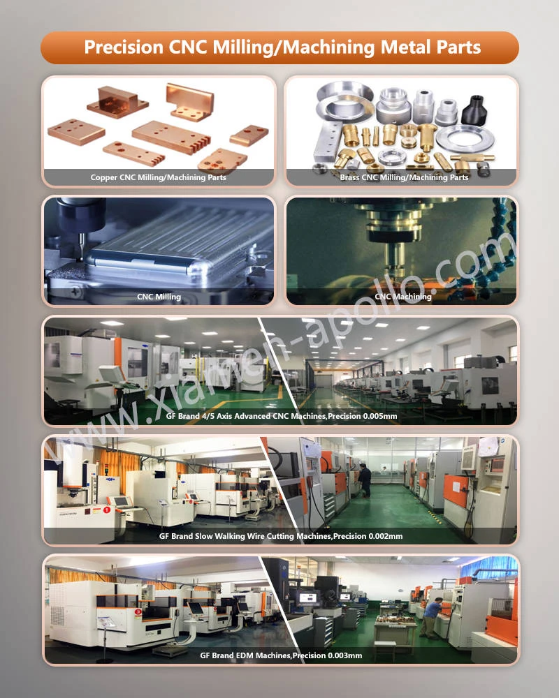
Five-axis CNC machining allows a component to be approached from multiple directions with fewer setups. For aluminum inverter housings, mounting interfaces and connector supports, this can reduce datum-transfer errors and provide access to angled surfaces, intersecting bores and complex cooling geometries.
Five-axis capability does not automatically produce better accuracy than three-axis machining. Machine calibration, fixture rigidity, tool length, thermal stability, workpiece geometry and inspection strategy remain the governing factors.
Selecting Between Three-Axis and Five-Axis CNC Machining
| Engineering requirement | Three-axis CNC | Five-axis CNC |
|---|---|---|
| Flat plates and simple pocketing | Often sufficient | May add unnecessary cost |
| Multiple faces requiring accurate alignment | May require repeated setups | Can reduce setup count |
| Angled ports or intersecting features | Requires suitable fixtures or additional operations | Offers more flexible tool orientation |
| Deep cavities | Depends on tool reach and access | Can improve access with suitable tool orientation |
| Thin-wall aluminum components | Feasible with appropriate clamping | Feasible, but tool access does not eliminate distortion risk |
| High-volume simple parts | Often cost-effective | Justified when geometry or setup reduction offsets machine cost |
| Accuracy control | Depends on setup and datum transfer | Depends on calibration, kinematics, fixturing and inspection |
Use five-axis machining when the part geometry or datum relationships justify it. For a simple plate with perpendicular holes, a well-controlled three-axis process may be more economical.
CNC Tolerance, Flatness and Surface-Finish Control
For aluminum CNC inverter parts, the drawing should distinguish functional tolerances from general machining tolerances. Typical initial design discussions may use ±0.05 mm for ordinary machined dimensions and tighter values such as ±0.01 mm for selected locating features, subject to geometry and capability studies.
The following controls should be specified where relevant:
- Datum strategy: Establish primary, secondary and tertiary datums that reflect actual assembly contact surfaces.
- Position tolerance: Use geometric dimensioning and tolerancing (GD&T) where hole patterns or mounting interfaces require positional control.
- Flatness: Define the permitted deviation for heat-sink bases, mating faces or sealing interfaces.
- Surface roughness: Specify the required finish for thermal contact, gasket sealing, sliding contact or coating preparation.
- Burr removal: Define edge breaks without allowing uncontrolled rounding of critical interfaces.
- Inspection method: Match CMM, optical measurement, bore gauges and surface-roughness instruments to the specified characteristics.
Surface roughness values such as Ra 1.6 μm or Ra 3.2 μm may be appropriate for selected machined surfaces, but neither value should be assigned indiscriminately. Thermal-interface requirements, gasket design and coating processes determine the appropriate target.
Managing Thin-Wall Deformation and Residual Stress
Thin-wall aluminum parts are susceptible to distortion when cutting forces release residual stress or when clamping pressure deforms the workpiece. These risks increase with asymmetric material removal, deep pockets and long unsupported walls.
A suitable process plan can include:
- Rough machining with balanced material removal.
- Intermediate stress-relief or stabilization where justified by the alloy condition and part geometry.
- Semi-finishing followed by controlled unclamping and dimensional verification.
- Finishing passes with reduced cutting load and a stable fixture arrangement.
- Final inspection after the component reaches a controlled temperature.
The need for stress relief must be evaluated against the alloy temper, heat-treatment history and allowable property changes. Thermal treatment should not be added without checking its effect on the specified mechanical condition.
CNC Machining and Stamping: Choosing the Production Route
| Factor | Aluminum stamping | Aluminum CNC machining |
|---|---|---|
| Best fit | Repeated sheet-metal geometries | Complex interfaces and precision features |
| Tooling investment | Die cost can be substantial | Fixtures and cutting tools are usually more flexible |
| Unit cost at high volume | Often favorable after tooling is amortized | Depends on cycle time and material removal |
| Material utilization | Can be high with optimized strip layout | Can be low for parts machined from solid stock |
| Design changes | May require die modifications | Often easier to implement through programming or fixture changes |
| Typical quality risks | Burrs, springback, cracking and feed variation | Tool wear, chatter, thermal drift and clamping distortion |
| Hybrid route | Stamped blank followed by selected finishing operations | Machined interfaces added to a formed or stamped component |
For a high-volume mounting bracket, stamping may be the better route. For an inverter connector support with multiple intersecting bores and accurately aligned threaded holes, CNC machining may be more appropriate. A hybrid process can combine stamped geometry with machined datums or tapped interfaces.
Anodizing and Corrosion Control for Outdoor Solar Equipment
Anodizing converts the aluminum surface into an aluminum-oxide layer through an electrochemical process. It can improve surface wear resistance and corrosion behavior, but coating selection must reflect the exposure environment, base alloy, geometry and required electrical function.
Anodizing is not a substitute for correct drainage, galvanic-corrosion control, fastener selection or mechanical design. Outdoor solar installations may experience condensation, temperature cycling, airborne salts, industrial contaminants and prolonged ultraviolet exposure of adjacent non-metallic materials.
Choosing an Anodizing Specification
| Surface-treatment option | Typical purpose | Engineering considerations |
|---|---|---|
| Sulfuric-acid anodizing | General corrosion protection and surface finish | Specify thickness, sealing, appearance and dimensional allowance |
| Hard anodizing | Higher surface hardness and wear resistance | Thicker coating can affect fit and dimensional requirements |
| Chemical conversion coating | Corrosion protection and coating preparation | Performance depends on the specified process and applicable compliance requirements |
| Anodizing followed by sealing | Reduces accessible porosity in the oxide layer | Sealing quality and coating consistency require process control |
| Masked anodizing | Preserves selected electrical or dimensional interfaces | Mask boundaries and exposed areas must be defined on the drawing |
A coating thickness of 10–15 μm may be a useful starting point for discussion for some general-purpose anodized components. The final requirement must be established through the relevant drawing, applicable standard, alloy response and environmental test plan.
Coating Thickness, Fit and Electrical Contact
The anodic oxide layer grows partly into the aluminum substrate and partly outward from the original surface. Therefore, coating thickness cannot be treated as a simple one-sided dimensional addition without considering the specified process and alloy.
For threaded holes, sliding interfaces and close-fitting slots, establish whether the feature is to be masked, machined after coating or dimensioned to accommodate the finish. Verify the final condition rather than relying solely on pre-treatment dimensions.
Anodized aluminum is generally electrically insulating at the coated surface relative to bare metal, but insulation performance varies with coating condition, defects, sealing and test conditions. Grounding points, bonding interfaces and electrical contacts should be designed and qualified accordingly.
Galvanic Corrosion Between Aluminum and Other Metals
Aluminum can corrode preferentially when electrically coupled to a more noble metal in the presence of an electrolyte. Risk depends on the material pair, exposed surface-area ratio, moisture retention and protective measures.
| Interface | Potential concern | Design or process control |
|---|---|---|
| Aluminum to stainless steel | Galvanic attack under wet or saline conditions | Evaluate compatible fasteners, isolation washers, coatings and drainage |
| Aluminum to copper | Elevated galvanic-corrosion risk in conductive moisture | Avoid uncontrolled direct contact in exposed wet areas; use suitable isolation or qualified interfaces |
| Aluminum to carbon steel | Corrosion of exposed steel and possible attack on adjacent aluminum | Select compatible protective finishes and prevent coating damage |
| Aluminum to polymer spacer | Usually limited direct galvanic interaction | Check moisture traps, compression, creep and long-term interface stability |
Material compatibility should be assessed for the actual installation environment. A material combination that performs adequately in an indoor assembly may not be suitable for coastal solar installations without additional protection.
ASTM B117 Salt-Spray Testing and Its Limits
ASTM B117 defines a controlled salt-spray apparatus and operating practice for evaluating the relative corrosion resistance of metallic and coated specimens. It does not establish a universal pass/fail duration for every solar mounting component.
A purchase specification should identify:
- The exact test method and specimen preparation.
- Whether the test applies to the coating, base material, fastener interface, or complete assembly.
- Test duration and inspection intervals.
- The acceptance criteria for corrosion, blistering, coating damage, or dimensional change.
- Any required post-test functional checks.
A claim such as "passed 1,000 hours of salt spray" is incomplete without the specimen condition, test method, and acceptance criteria. Salt-spray results should not be treated as a direct prediction of service life in every outdoor environment.
Consult Our Electrical Engineers Today
Frequently Asked Questions
Which aluminum alloy is suitable for solar mounting brackets and inverter components?
5052 is commonly considered for formed sheet-metal brackets and covers; 6061-T6 is often used for CNC-machined interfaces; and 6063 is widely used for extruded rails and profiles.
What anodizing thickness should be specified for outdoor solar mounting metal components?
A 10–15 μm anodizing thickness can serve as an initial discussion range for some general-purpose components, but it is not a universal requirement.
What information is required to quote custom aluminum stamping and CNC machining in China?
Provide the 2D drawing, 3D model if available, alloy and temper, surface finish, critical tolerances, prototype quantity, annual demand and packaging requirements. State whether tooling, first-article inspection, material certificates and regulatory documentation must be included in the quotation.
contact us
For production planning, submit the current drawing revision, alloy and temper, annual demand, surface-treatment specification and critical inspection requirements. Request a process review covering aluminum stamping, CNC Machining Service For Aluminum Metal Parts, anodizing, dimensional verification and production tooling so the manufacturing route can be evaluated before tooling commitment and mass-production release.