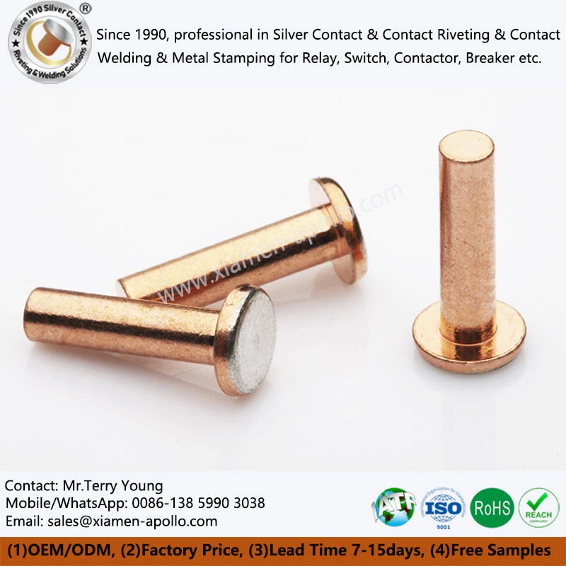
Cold Headed Bimetal Contacts can reduce machining waste and shorten cycle times by forming metal through plastic deformation rather than removing material through cutting. For high-volume electrical contact production, the actual cost advantage depends on silver content, rivet geometry, dimensional tolerances, material utilization, tooling life, and the required production volume. Machining remains useful for complex geometries and low-volume parts, while multi-station cold heading generally suits repeatable, high-volume solid rivets and bimetal contact components.
Cold Heading vs. Machining: Production Rate and Process Economics
The primary difference between cold heading and machining is how each process converts metal stock into a finished component. Cold heading forces wire or rod stock into a die cavity, while machining removes material with cutting tools to achieve the specified geometry.
For silver contacts, this distinction affects cycle time, raw-material consumption, burr formation, dimensional consistency, and the cost of downstream finishing.
Process Comparison for Silver Contact Rivets
| Evaluation Factor | Multi-Station Cold Heading | CNC Turning or Machining |
|---|---|---|
| Material conversion | Plastic deformation in dies | Material removal by cutting |
| Typical production suitability | Medium- to high-volume orders | Prototypes, low-volume orders, complex geometries |
| Material utilization | High when blank design is optimized | Lower when substantial stock must be removed |
| Cycle time | Short, repeatable forming cycles | Depends on cutting time and tool changes |
| Tooling investment | Dedicated dies and process setup | Cutting tools, fixtures, and CNC programming |
| Geometry flexibility | Limited by die design and forming capability | High for accessible turned features |
| Surface condition | Depends on stock quality, die finish, and lubrication | Depends on tool condition, cutting parameters, and finishing |
| Dimensional control | Die geometry, wire diameter, feed, and station alignment | Machine accuracy, tool wear, workholding, and compensation |
| Scrap management | Trim scrap and setup losses may occur | Chips and machining allowance generate scrap |
| Economic advantage | Repeated production with stable geometry | Low-volume or geometry-intensive work |
You can't reliably compare production rates using a universal parts-per-minute figure. A cold heading machine's output depends on the number of stations, forming complexity, feed system, machine speed, inspection requirements, and downtime. CNC output depends on cycle time, tool changes, workholding, and the number of parts produced per cycle.
For a fair comparison, evaluate accepted parts per operating hour rather than relying on nominal machine speed. Exclude rejected components and account for setup, tooling adjustments, stoppages, and inspection delays.
Cycle Time and Annual Production Capacity
A single-station machining process may require several operations to form a rivet head, shank, and end profile. Multi-station cold heading can distribute deformation across successive dies, reducing the need for separate machining operations when the geometry permits.
| Production Variable | Cold Heading | Machining |
|---|---|---|
| Main cycle-time drivers | Feed, transfer, deformation, ejection | Cutting passes, tool changes, loading, unloading |
| Secondary operations | Trimming, sizing, cleaning, inspection as required | Deburring, finishing, cleaning, inspection as required |
| Capacity bottlenecks | Die wear, wire feeding, transfer faults | Tool wear, chip removal, spindle availability |
| Best comparison metric | Accepted parts per hour | Accepted parts per hour |
High-speed equipment does not automatically deliver lower unit costs. If a contact requires tight concentricity, a complex undercut, or a feature that cannot be formed reliably, secondary machining may still be necessary.
The process decision should therefore be based on the complete production route, not the primary machine's rated speed.

Material Utilization: Reducing Silver and Copper Waste
Material utilization is often the largest economic variable when manufacturing silver contact rivets, particularly when the contact head contains a high proportion of silver. Cold heading can reduce cutting waste by displacing metal into the required shape instead of removing it as chips.
However, material savings must be assessed against the actual component geometry and the complete production route.
Comparing Material Yield for Solid Contact Rivets
Material yield can be assessed by comparing the net mass of accepted finished components with the total mass of raw material consumed over the same production period.
Consider a hypothetical production example:
| Parameter | Machining Route | Cold Heading Route |
|---|---|---|
| Raw material consumed | 100 kg | 100 kg |
| Net mass of accepted parts | 65 kg | 88 kg |
| Calculated material yield | 65% | 88% |
| Material not retained in accepted parts | 35 kg | 12 kg |
These figures are illustrative, not measured production results or guaranteed process performance. Actual yield depends on rivet dimensions, head-to-shank ratio, blank design, setup scrap, rejected parts, and the recovery of machining chips or heading scrap.
The comparison also needs a consistent accounting boundary. If machining chips are recycled, their recoverable metal value should be credited separately rather than treating all removed material as an unrecoverable loss.
Why Silver Content Changes the Cost Calculation
For a solid silver contact, reducing material loss can have a direct effect on material cost because silver contributes substantially to the raw-material value. For a copper-shank rivet with a silver contact head, the financial benefit depends on the silver mass saved, not simply the total mass of the component.
A practical cost comparison should consider the quantity of material saved and its applicable material price, then account for scrap recovery, forming yield, tooling amortization, energy consumption, inspection, and secondary operations.
| Component Type | Primary Cost Driver | Key Process Consideration |
|---|---|---|
| Solid silver contact rivet | Silver mass and forming yield | Minimize silver loss while maintaining head geometry |
| Silver-head, copper-shank rivet | Silver head mass and bond integrity | Control silver distribution and head-to-shank interface |
| Silver-alloy contact rivet | Alloy composition and contact duty | Match material grade to electrical switching conditions |
| Copper contact rivet | Copper mass and forming yield | Control dimensions, hardness, and electrical resistance |
Bimetal Cold Heading and Silver Distribution
Bimetal cold heading combines dissimilar conductive materials in a formed component. In silver-head, copper-shank contact rivets, the silver-bearing section provides the contact surface while the copper shank provides the mounting interface and a conductive path.
The process must maintain the specified silver volume, head profile, concentricity, and interface integrity. An apparently acceptable external head does not prove that the internal bond or material distribution is correct.
Relevant inspection points include:
- Silver-head diameter and height, measured against the drawing.
- Head-to-shank concentricity and shank straightness.
- Interface integrity, evaluated by an appropriate cross-section or destructive test.
- Contact surface condition and visible forming defects.
- Material composition and lot traceability.
For a design change intended to reduce silver consumption, engineering approval should follow verification of the contact dimensions and electrical performance under the intended switching conditions.
Download Contact Material Spec Sheet
Metal Flow, Work Hardening, and Dimensional Stability
Cold heading changes the metal through plastic deformation. Depending on the alloy, reduction ratio, forming sequence, and intermediate annealing, the process can increase hardness and strength through work hardening.
Machining, by contrast, creates a new surface by removing material. Its effects on the remaining component depend on cutting conditions, tool condition, residual stress, and the original material condition.
Metal Flow Lines in Cold-Formed Rivets
In a cold-headed rivet, material flow follows the deformation path imposed by the dies. When the blank and die design are appropriate, the resulting flow pattern can follow the head and shank geometry instead of being interrupted by extensive cutting.
This does not mean that cold heading always produces superior fatigue resistance or eliminates defects. Excessive deformation, poor lubrication, unsuitable stock, or an incorrect forming sequence can cause laps, folds, surface cracking, or internal damage.
| Engineering Variable | Cold Heading Consideration | Machining Consideration |
|---|---|---|
| Grain-flow pattern | Influenced by deformation path and die geometry | Depends on original stock; cutting removes material across the existing structure |
| Work hardening | Can increase local hardness and strength | Cutting may create a localized altered layer, depending on conditions |
| Residual stress | Depends on deformation, tooling, and any subsequent heat treatment | Depends on cutting forces, heat, and stress release |
| Surface defects | Laps, folds, cracks, and die marks | Burrs, chatter marks, tool marks, and built-up edge |
| Dimensional stability | Influenced by springback, die wear, and material variation | Influenced by tool wear, clamping, temperature, and compensation |
Hardness and Microstructure Verification
Hardness is not a substitute for electrical contact testing. Excessive work hardening can also affect subsequent forming, joining, or assembly operations.
Where hardness is a controlled characteristic, the drawing or control plan should specify the applicable test method, test location, material condition, and acceptance range. Vickers microhardness testing under ASTM E384 may be appropriate for localized measurements when the specimen geometry and preparation permit it.
| Inspection Item | Suggested Verification Approach | Engineering Purpose |
|---|---|---|
| Bulk hardness | Applicable Rockwell or Vickers method | Verify material condition |
| Local hardness gradient | ASTM E384 microhardness, where applicable | Identify localized deformation effects |
| Surface cracking | Optical inspection and suitable nondestructive testing | Detect forming-related defects |
| Internal folds or laps | Metallographic sectioning and microscopy | Evaluate die design and forming sequence |
| Dimensional stability | Repeated measurements across production lots | Detect tool wear or material variation |
The acceptance criteria must come from the approved drawing, material specification, or validated process-control plan. ASTM E384 defines a test method; it does not establish a universal hardness requirement for every silver contact rivet.
Tolerance Control Across the Forming Sequence
A cold-heading process may control head diameter and shank dimensions efficiently, but the achievable tolerance is part-specific. Wire diameter variation, die clearance, transfer accuracy, elastic recovery, and tool wear all influence the final dimensions.
A nominal tolerance such as ±0.01 mm should not be promised without evidence from production capability studies. If the design includes critical concentricity, head height, or interface dimensions, those features should be measured using a method suited to their geometry.
For production qualification, establish:
- The critical-to-quality dimensions and their drawing tolerances.
- The measurement method, instrument resolution, and calibration status.
- Initial capability and ongoing process monitoring where applicable.
- Tool-life limits and inspection frequency.
- A reaction plan for out-of-tolerance results.
For applicable automotive supply chains, IATF 16949 requirements and customer-specific requirements may govern process approval, traceability, and change control. Certification alone does not demonstrate that a particular component meets its drawing.

Multi-Station Cold Heading: Throughput and Tooling Control
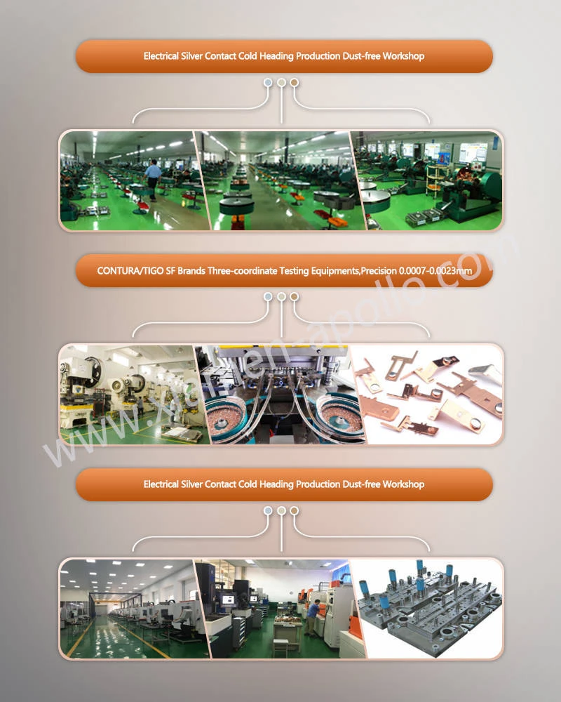
Multi-station cold heading divides the forming operation among successive stations. Each station performs a defined deformation step, such as upsetting, preforming, head forming, or sizing. This arrangement can produce high output when the component geometry, material condition, and transfer sequence are suitable.
Claims of million-piece daily production must be tied to a specific part, machine configuration, operating schedule, and quality acceptance rate.
Tooling Life, Lubrication, and Process Stability
High-volume cold heading transfers part of the production-cost risk from cutting time to tooling design, tooling life, and process stability. Die wear can change head dimensions, shank geometry, surface finish, and forming loads.
Control plans should monitor variables that directly affect part quality:
- Wire or rod diameter and incoming material condition.
- Die wear and the replacement criteria for critical tooling.
- Lubrication condition and contamination.
- Transfer timing, ejection, and abnormal forming loads.
- First-piece approval and in-process dimensional inspection.
- Batch identification and nonconforming-product containment.
Tooling life should be recorded against actual production counts and defect history. A tool-life estimate without a defined wear limit and inspection method is not a reliable basis for a production quotation.
Comparing Total Manufacturing Cost
The lowest machining time or highest nominal heading speed does not necessarily produce the lowest accepted-part cost. The comparison should include all cost elements that differ between the routes.
| Cost Component | Cold Heading | Machining |
|---|---|---|
| Raw-material consumption | Blank design and forming yield | Stock allowance and removed material |
| Tooling | Forming dies, punches, guides | Cutting tools, fixtures, and holders |
| Labor | Setup, monitoring, maintenance | Programming, setup, loading, monitoring |
| Secondary processing | Sizing, trimming, cleaning as required | Deburring, finishing, cleaning as required |
| Scrap credit | Forming and setup scrap recovery | Chip segregation and metal recovery |
| Quality costs | Die wear, forming defects, dimensional drift | Tool wear, burrs, chatter, dimensional drift |
| Capital utilization | High throughput on suitable parts | Flexible production across varied geometries |
For procurement decisions, request quotations based on the same drawing revision, material grade, annual demand, packaging specification, inspection plan, and delivery terms. Comparing different assumptions can make either process appear artificially inexpensive.
Consult Our Electrical Engineers Today
Frequently Asked Questions about Cold Headed Electrical Contacts
What is the typical minimum order quantity (MOQ) for custom Cold Headed Parts?
Standard production runs typically start at 1,000 pieces to absorb multi-station tooling setup costs efficiently, though prototype sample batches can be arranged upon engineering request.
How do you verify the silver layer thickness and metallurgical bonding quality?
We utilize advanced metallographic microscope cross-section analysis and X-ray fluorescence (XRF) coating thickness measurements in compliance with ASTM standards to ensure 100% metallurgical integrity.
What are your standard lead times for custom OEM tooling and sample approval?
Initial tooling design and sample delivery for custom cold-headed contact components typically require 10 to 15 business days, depending on geometric complexity and material selection.
contact us
For an OEM production quotation, submit the Cold Headed Bimetal Contacts drawing, material grade, annual demand, critical tolerances, electrical duty, and inspection requirements. Request a documented comparison of cold heading and machining before approving the production route.