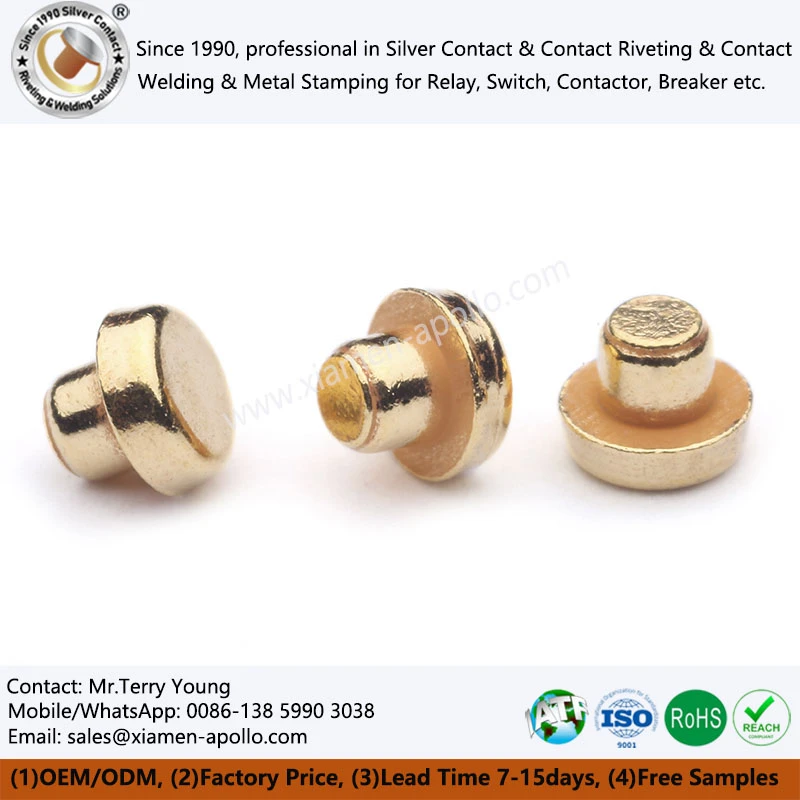
Electrical contact plating controls surface oxidation, contact resistance, wear behavior and long-term connection stability. Gold, silver and tin plating serve different electrical and mechanical requirements; coating selection must account for current, contact force, switching frequency, mating cycles, base-metal compatibility and the operating environment. For electrical contact manufacturers and OEM purchasing teams, coating thickness, adhesion, porosity and verification methods should be specified before production release.
How Electroplating Affects Electrical Contact Performance
Electroplating deposits a controlled metallic layer onto a conductive substrate to modify its surface properties without changing the entire component's bulk material. In relay contacts, copper terminals, stamped connectors and silver contact rivets, the coating influences both electrical conduction at the interface and the rate at which the surface degrades.
Contact resistance and surface-film formation
Contact resistance depends on the real area of metallic contact, contact force, surface roughness, contamination and the properties of the surface film. Although a contact may have a large apparent area, electrical current passes through a much smaller number of microscopic contact spots.
Silver provides high electrical conductivity, but silver sulfide can form in sulfur-containing atmospheres. Gold resists oxidation and is suitable for low-level signal contacts, while tin provides a practical surface for many separable copper connections but can develop oxide films and fretting-related resistance under certain conditions.
| Plating material | Typical electrical characteristic | Main surface‑related risk | Common engineering use |
|---|---|---|---|
| Silver (Ag) | High conductivity; bulk resistivity approximately 1.59 μΩ·cm at 20°C | Sulfidation and surface tarnishing | Power contacts, relay contacts, conductive terminals |
| Gold (Au) | High conductivity; bulk resistivity approximately 2.44 μΩ·cm at 20°C | Wear‑through, porosity and high material cost | Low‑level signals, precision connectors, control circuits |
| Tin (Sn) | Bulk resistivity approximately 11.5 μΩ·cm at 20°C | Oxide formation, fretting and tin whiskers in susceptible systems | Copper terminals, stamped connectors, wire‑termination interfaces |
Oxidation, sulfur exposure and corrosion testing
Coating performance depends on the chemical species present in the service environment. Silver can tarnish in sulfur-bearing atmospheres; tin oxide may increase resistance at low contact forces; and gold's corrosion resistance can be compromised by pores exposing the underlying substrate.
Salt spray testing under ASTM B117 evaluates corrosion behavior in a controlled salt-fog environment. However, it does not directly predict performance in sulfur-rich industrial atmospheres, mixed flowing gas environments or actual electrical switching duty. Test methods should therefore match the failure mechanism expected in service.
For electrical contact plating suppliers, qualification should distinguish cosmetic discoloration from measurable increases in contact resistance, corrosion through the coating and loss of mechanical integrity.
Wear resistance and mating-cycle requirements
Plating thickness must be selected against the expected mechanical and electrical duty rather than a generic coating specification.
- Gold-plated signal contacts: Define the minimum local gold thickness, mating-cycle target and allowable resistance change.
- Silver-plated switching contacts: Evaluate arc erosion, transfer of material between contacts, thermal loading and contact force.
- Tin-plated copper stamping: Evaluate insertion force, fretting exposure, oxide-film behavior and the intended connection system.
A thicker coating does not automatically provide a longer service life. Adhesion, porosity, deposit hardness, surface roughness and the distribution of contact pressure can be equally important.
Gold vs. Silver vs. Tin: Selecting the Correct Plating System
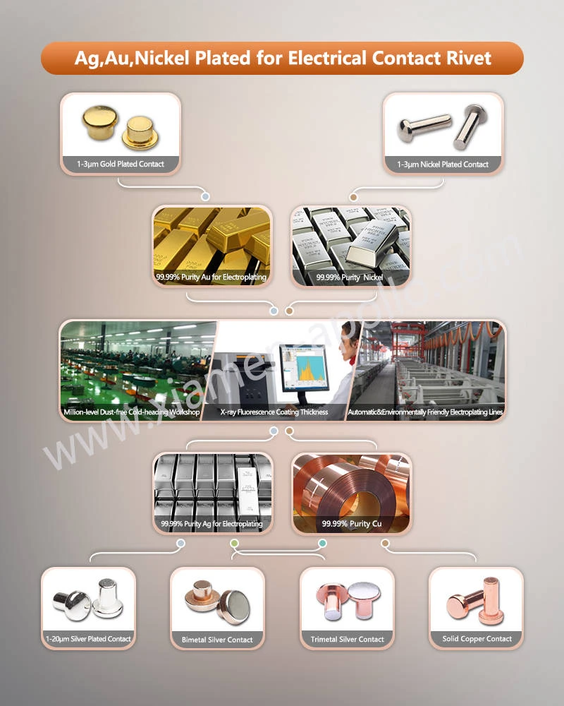
The correct coating depends on the electrical duty, contact geometry, substrate, environmental conditions and target service life. Gold is generally selected for stable low-level signal interfaces, silver for conductive power paths, and tin for many cost-sensitive copper connection systems.
Gold plating for low-level signals and precision connectors
Gold is useful when a contact must maintain a low and stable interface resistance under low-voltage, low-current conditions. It does not readily form the tenacious insulating oxide films associated with many base metals.
Gold plating specifications should distinguish between hard gold alloy deposits and softer, high-purity gold deposits. Hard gold, often alloyed with small quantities of other metals, is commonly used for repeated mating. Softer gold may be appropriate for applications with limited mechanical wear.
Key specification variables include:
- Minimum local gold thickness, measured in micrometres (μm).
- Gold composition and deposit hardness.
- Nickel or other qualified barrier-layer thickness where required.
- Porosity and exposed-substrate acceptance criteria.
- Mating cycles, contact force and allowable contact-resistance change.
A nominal average thickness alone may not protect edges, stamped corners or high-wear regions. The drawing should define the measurement locations and the acceptance criteria for minimum thickness.
Silver plating for relay contacts and power terminals
Silver is widely used where low electrical resistance and current-carrying capability are priorities. Silver-plated contact rivets, copper terminals and relay components can provide a conductive surface while retaining a copper-based structural substrate.
The plating specification must account for the difference between a silver-plated surface and a solid silver contact. A plated copper part has a functional surface coating over a conductive base metal; a bimetal contact rivet may instead use a silver contact layer joined to a copper shank through a forming or bonding process.
| Design factor | Silver‑plated copper | Bimetal silver contact rivet | Solid silver contact |
|---|---|---|---|
| Silver distribution | Surface coating | Localized contact layer | Bulk silver |
| Primary cost variable | Coating area and thickness | Silver head geometry and bond integrity | Silver mass |
| Main qualification focus | Adhesion, porosity and thickness | Bond strength, interface integrity and contact wear | Geometry, material grade and wear |
| Typical use | Conductive terminals and connector parts | Relay and switch contact assemblies | Applications requiring a solid silver contact body |
For switching devices, silver plating should not be treated as a substitute for the correct contact material. Arc energy, switching current, load inductance, opening speed and contact geometry may require a silver alloy such as AgSnO₂ or AgNi rather than a pure silver coating.
Tin plating for copper stamping and electrical terminals
Tin plating is widely applied to copper and copper-alloy stamped parts because it supports practical electrical joining and is compatible with many soldering and terminal-connection processes.
However, tin is not universally suitable for low-level signal contacts. Tin oxide can affect interface resistance, particularly where contact force is insufficient to disrupt the surface film. Fretting caused by vibration or thermal movement can also generate wear debris and unstable resistance.
Tin-plated copper stamping specifications should define:
- Tin deposit thickness and whether the finish is matte or bright.
- Copper substrate grade and temper.
- Underplating or barrier-layer requirements, where applicable.
- Solderability or crimping requirements for the intended connection.
- Whisker-risk assessment for susceptible geometries and operating conditions.
Tin whisker control requires particular attention in closely spaced conductors and sensitive electronic assemblies. Applicable mitigation measures should be selected through design review and qualification testing rather than assuming that a particular nominal thickness eliminates the risk.
Material selection by operating condition
| Operating condition | Preferred starting point | Engineering checks |
|---|---|---|
| Low‑level signal, low contact force | Gold‑plated contact | Minimum gold thickness, porosity, mating cycles and resistance stability |
| High‑current conductive interface | Silver‑plated copper or a silver‑alloy contact system | Temperature rise, current density, contact force and corrosion exposure |
| Solderable copper terminal | Tin‑plated copper stamping | Solderability, coating thickness, storage conditions and substrate compatibility |
| Repeated switching with electrical arcs | Application‑qualified silver alloy contact | Arc erosion, welding tendency, transfer, temperature and endurance |
| Vibrating separable connection | Application‑qualified gold or tin system | Fretting, contact force, surface finish and vibration profile |
These are initial selection guidelines, not universal prescriptions. Final selection should be validated against the product's electrical rating, applicable IEC requirements and the actual operating environment.
Download Contact Material Spec Sheet
Plating Thickness, Adhesion and Corrosion Verification
Coating thickness and adhesion are separate quality characteristics. A coating can meet its nominal thickness requirement but fail because of poor surface preparation, excessive internal stress, inadequate activation or incompatibility between the coating and substrate.
Defining coating thickness and measurement locations
The engineering drawing should specify the coating material, minimum local thickness, measurement method and functional measurement locations. Where a barrier layer is used, its thickness should be controlled separately from the functional outer coating.
| Verification item | Typical method or reference | What it establishes | Important limitation |
|---|---|---|---|
| Metallic coating thickness | X-ray fluorescence (XRF); ISO 3497 | Non-destructive thickness measurement where the coating system and geometry are suitable | Results depend on calibration, layer composition and measurement geometry |
| Cross-sectional thickness | Metallographic cross-section; ISO 1463 | Layer thickness and interface structure at the examined location | Destructive and limited to the prepared section |
| Adhesion of electrodeposited coatings | ISO 2819 or a specified coating-specific method | Resistance to separation under the selected test | Method suitability depends on substrate, coating and part geometry |
| Corrosion resistance | ASTM B117 or a specified cyclic-corrosion method | Corrosion behavior under defined exposure conditions | Does not directly establish electrical endurance in service |
| Solderability, where relevant | Applicable IEC 60068-2-20 method or customer specification | Wetting behavior under the specified soldering conditions | Not a substitute for contact-resistance or bond-strength testing |
No single standard covers every plating system and component geometry. The drawing and inspection plan should identify the applicable edition, test conditions, sample size and acceptance limits.
XRF thickness measurement and cross-sectional analysis
XRF is suitable for routine inspection of many metallic coatings when the coating composition, substrate and measurement geometry are supported by the instrument's calibration. For multilayer systems, the measurement method must distinguish the individual layers or use a validated model.
Cross-sectional microscopy provides direct evidence of coating thickness, layer continuity and the interface between the coating and substrate. It is particularly useful during process validation, failure analysis and investigation of edge coverage or localized delamination.
A production inspection plan should specify:
- Measurement locations, including edges or contact zones where functional.
- Minimum local thickness and permitted variation.
- Calibration standards and measurement frequency.
- Cross-section preparation and evaluation criteria when required.
- Traceability between the inspection results and production lot.
Adhesion tests and bend-test limitations
Adhesion failure can originate from inadequate cleaning, incomplete activation, contamination, excessive deposit stress or poor compatibility between adjacent layers.
A bend test may be useful for suitable sheet-metal specimens, but it is not a universal acceptance method for plated electrical contacts. Bending radius, substrate thickness, ductility and coating thickness all affect the result. Small stamped parts may require a customer-approved test method or a representative process coupon.
The acceptance criteria should define the permissible condition after testing, such as no visible flaking or separation under a specified inspection method. If the functional coating is required to remain intact during deformation, that requirement must be explicit.
ASTM B117 salt spray and service-environment qualification
ASTM B117 defines a controlled salt-fog exposure procedure. It is useful for comparing corrosion behavior under specified conditions, but it does not establish a universal pass/fail duration for all gold-, silver- or tin-plated components.
For example, a salt-fog test may not reproduce silver sulfidation, mixed-gas exposure, condensation cycles or electrical arcing. Where those mechanisms govern service life, qualification should include an appropriate environmental test and, when necessary, measurements of contact resistance before and after exposure.

Cyanide-Free Electroplating and Environmental Compliance
Electroplating chemistry affects worker safety, wastewater treatment, process controls and environmental compliance. Cyanide-free processes can reduce specific cyanide-related hazards, but the term does not establish that an entire plating operation is environmentally harmless or automatically compliant with every applicable regulation.
Cyanide-free silver plating: process qualification
Conventional silver-plating processes may use cyanide-based electrolytes. Alternative chemistries are available, but their suitability depends on the substrate, deposit properties, component geometry and production requirements.
A cyanide-free process should be qualified against the same functional criteria as any other plating system:
- Coating thickness and uniformity across functional surfaces.
- Adhesion and resistance to flaking.
- Surface appearance and deposit composition.
- Electrical contact resistance and environmental stability.
- Bath stability, wastewater controls and process repeatability.
A chemistry change can affect deposit morphology, throwing power, porosity and process-window stability. Existing process parameters should not be assumed to transfer unchanged when a plating chemistry is replaced.
RoHS, REACH and substance declarations
RoHS and REACH address different regulatory requirements. RoHS restricts specified hazardous substances in electrical and electronic equipment within its scope, while REACH governs chemicals and related obligations, including applicable restrictions and substance communication requirements.
A claim of "RoHS compliant" or "REACH compliant" should be supported by relevant declarations and material information for the applicable product and market. The claim should not be inferred solely from the absence of cyanide in the plating bath.
For OEM supplier qualification, the documentation package may include:
- Plating chemistry and relevant process declarations.
- Substrate and coating material declarations.
- Applicable RoHS and REACH documentation.
- Restricted-substance information from upstream material suppliers.
- Lot identification and traceability records.
- Process-change notification and requalification requirements.
Production controls and supplier audit points
An electrical contact plating supplier should demonstrate control of the process from substrate preparation through final inspection. The audit should focus on the documented process and actual production records rather than certifications alone.
| Audit item | Evidence to request | Engineering purpose |
|---|---|---|
| Pre-plating preparation | Cleaning, activation and rinse-control records | Reduce contamination and adhesion failures |
| Bath management | Composition, temperature, pH where applicable, and replenishment records | Maintain deposit consistency |
| Thickness control | XRF calibration, inspection results and sampling plan | Verify coating requirements |
| Adhesion and corrosion | Test procedures, results and corrective-action records | Confirm process qualification |
| Material compliance | Applicable RoHS/REACH declarations | Support regulatory assessment |
| Traceability | Lot codes, inspection records and process-change history | Enable containment and failure investigation |
ISO 9001 and IATF 16949 may support documented quality management, depending on the supplier's certification scope. Neither certification by itself proves that a specific plating thickness, adhesion result or environmental test requirement has been met.
Consult Our Electrical Engineers Today
Frequently Asked Questions
How is the thickness of gold, silver or tin plating on electrical contacts measured?
X-ray fluorescence (XRF) is commonly used for non-destructive thickness measurement when the coating system and geometry are suitable. Cross-sectional microscopy can verify layer thickness and interfaces.
Which plating tests should an electrical contact manufacturer provide for OEM qualification?
The test plan depends on the application. Typical evidence includes coating-thickness measurements, adhesion tests, corrosion testing, and applicable material declarations.
Can a China electrical contact plating supplier provide RoHS/REACH documentation and production traceability?
A qualified supplier should be able to provide applicable material declarations and lot-level production records when these are included in its quality system and supply agreement.
contact us
Submit your Gold Coating Electrical Contacts drawing, substrate grade, required coating metal, minimum thickness, and operating conditions for a technical review. Request a quotation covering plating feasibility, inspection methods, sample validation, and production capacity before finalizing your next electrical contact order.