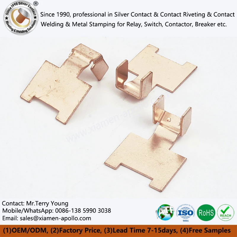
Punching Metal Stamping Copper Contact Parts combined with localized CNC machining provides a practical manufacturing route for complex electrical terminals that require both cost control and dimensional precision. Progressive die stamping reduces material waste and unit costs in repeat production, while CNC machining controls critical features such as threaded holes, mounting interfaces, and contact surfaces. The optimal process depends on production volume, copper utilization, tolerance requirements, tooling investment, and electrical performance criteria. This article examines process selection, hybrid manufacturing strategies, cost break-even analysis, and supplier evaluation for OEM electrical terminal projects.
Stamping vs. CNC Machining: Where Does the Cost Break-Even Point Occur?
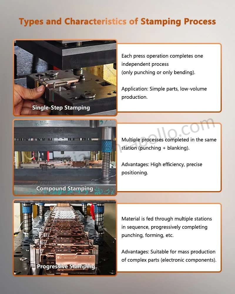
Progressive die stamping generally reduces unit costs for repeat-production electrical terminals by distributing tooling costs across large quantities. CNC machining is more suitable for low-volume parts, complex three-dimensional features, and geometries that require tight dimensional control. Combining stamped preforms with localized CNC machining can reduce material waste and machining time while retaining precision at critical electrical interfaces.
The correct process depends on annual demand, material utilization, dimensional tolerances, feature geometry, tooling investment, and inspection requirements. There is no universal production-volume threshold at which stamping becomes cheaper than CNC machining; the break-even point must be calculated from the actual part design and production conditions.
Progressive Die Stamping: High-Volume Production and Material Utilization
Progressive die stamping forms sheet metal through sequential operations, including blanking, piercing, bending, coining, and forming. The workpiece advances through multiple stations, allowing several features to be produced within one press cycle.
For copper and brass electrical terminals, stamping is appropriate for geometries with repeatable planar features, formed tabs, mounting holes, and spring sections.
Key engineering considerations include:
- Material thickness: Common terminal stock may range from 0.3–3.0 mm, subject to alloy, part geometry, and press capability.
- Dimensional tolerance: A tolerance of ±0.02 mm may be achievable for selected stamped features, but the drawing, material condition, burr direction, and tooling design determine actual capability.
- Burr control: Punch-to-die clearance and tool wear affect burr height, edge quality, and assembly consistency.
- Tooling amortization: Progressive dies require upfront engineering and manufacturing investment, which must be allocated across expected production volume.
- Strip layout: Nesting efficiency and carrier design affect material yield, scrap generation, and dimensional stability.
Stamping becomes economically attractive when the production volume is sufficient to offset die costs and when the part geometry can be produced without excessive secondary operations.
CNC Machining: Geometric Flexibility and Localized Precision
CNC milling and turning remove material from bar stock, plate, or a preformed workpiece. The process supports complex contours, threaded holes, precision bores, and localized surface features that may be difficult to produce economically through stamping alone.
CNC machining is commonly considered for prototypes, engineering revisions, small production batches, and electrical terminals with demanding interface dimensions.
Important cost drivers include:
- Machining time: Deep pockets, multiple tool changes, and difficult-to-access surfaces increase cycle time.
- Material removal: Machining a terminal from solid copper or brass stock can generate substantial chips.
- Workholding: Thin or asymmetrical parts may require dedicated fixtures to prevent deformation.
- Dimensional control: Tolerances such as ±0.01 mm may be feasible for selected features under controlled conditions, but must be validated for the material, geometry, and inspection method.
- Conductive interface finish: Burrs, tool marks, contamination, and surface damage can affect contact resistance and joint consistency.
CNC machining is not inherently more expensive for every part. A simple terminal with a low annual demand may cost less to machine than to produce with a dedicated progressive die.
Process Comparison: Stamping vs. CNC Machining
| Engineering factor | Progressive die stamping | CNC machining |
|---|---|---|
| Initial tooling cost | Higher; die design and fabrication required | Lower for standard setups; fixtures may be needed |
| Unit cost at high volume | Generally low after tooling amortization | Often higher due to cycle time and material removal |
| Unit cost at low volume | Can be high because of tooling allocation | Often competitive for simple setups |
| Typical geometry | Sheet-based profiles, bends, tabs, holes | Pockets, bores, threads, complex contours |
| Material utilization | Can be high with optimized strip layout | Depends on stock geometry and material removal |
| Thin-wall features | Suitable when supported by tooling and material properties | Possible, but workholding and deformation require control |
| Repeatability | Strong when tooling and process conditions remain stable | Strong with controlled programs, fixtures, and inspection |
| Design changes | May require die modifications | Often implemented through program revisions |
| Suitable applications | High-volume relay terminals and stamped copper connectors | Precision terminal interfaces, threaded features, and prototypes |
For procurement teams, comparing quoted unit prices without examining tooling charges, scrap assumptions, inspection scope, and expected annual demand can lead to incorrect sourcing decisions.
Stamping Preforms + Localized CNC Machining: A Hybrid Manufacturing Route
A hybrid manufacturing route uses stamping to create the main terminal profile and CNC machining to finish only the features that require tighter dimensional control. This avoids machining the entire part from solid stock while preserving precision at threaded holes, mounting interfaces, contact surfaces, and selected reference datums.
The approach is particularly relevant to high-current electrical terminals where bulk conductivity, mechanical attachment, and interface geometry must be controlled simultaneously.
Establishing the Division of Manufacturing Operations
The most economical process sequence assigns each feature to the manufacturing method best suited to its geometry and tolerance.
| Feature or requirement | Preferred operation | Engineering reason |
|---|---|---|
| Outer terminal profile | Blanking or progressive stamping | Efficient production of repeatable sheet-based geometry |
| Mounting tabs and bends | Progressive die stamping | Multiple formed features can be produced in one production sequence |
| Standard clearance holes | Piercing | Avoids unnecessary drilling and chip generation |
| Precision threaded holes | CNC drilling and tapping | Provides control over thread dimensions and engagement |
| Critical locating surfaces | CNC milling | Controls selected datums and mating dimensions |
| Local contact or clamping interface | CNC milling or turning, where applicable | Improves geometric control at the specified interface |
| Deburring | Controlled mechanical or other qualified finishing | Reduces burr-related assembly and electrical risks |
| Final dimensional verification | CMM, gauges, or optical inspection | Confirms compliance with drawing requirements |
Not every stamped terminal needs CNC finishing. Secondary machining should be limited to features for which the tolerance, geometry, surface condition, or assembly requirement justifies the added operation.
Datum Design and Tolerance Allocation
The hybrid process introduces a critical engineering question: how will the CNC operation locate the stamped preform?
Stamped parts may exhibit springback, local distortion, and variation in formed angles. If a fixture references an unstable surface, the final machined feature can shift relative to the functional mounting or contact interface.
The design and process plan should define:
- Primary datum: The surface or feature that establishes the main locating reference.
- Secondary datum: The feature that controls lateral position or orientation.
- Tertiary datum: The feature that constrains the remaining degree of freedom.
- Fixture contact points: Locations that support the part without causing permanent deformation.
- Machining allowance: The stock available to remove stamping variation while retaining minimum wall thickness.
- Inspection strategy: The datum reference frame and geometric tolerances used to verify the finished part.
A drawing tolerance of ±0.01 mm on a machined hole does not automatically guarantee the same positional accuracy relative to the stamped outer profile. The entire datum chain must be evaluated.
For complex terminals, geometric dimensioning and tolerancing (GD&T) can be used to define position, perpendicularity, flatness, and profile requirements relative to functional assembly datums.
Managing Burrs, Springback, and Contact Resistance
The transition between stamping and CNC machining can introduce defects if the process sequence is not controlled.
A stamped burr can interfere with fixture seating, while clamping pressure can deform thin copper sections. Machining may also introduce chips or cutting-fluid residues that contaminate conductive interfaces.
Recommended controls include:
- Specify the permissible burr height and direction on the engineering drawing.
- Define whether deburring occurs before or after secondary machining.
- Use fixture supports close to the machining load to reduce local deformation.
- Remove chips and process residues before electrical contact surfaces are assembled.
- Verify critical hole positions and interface flatness after machining.
- Measure contact resistance on the assembled joint under defined clamping force, surface condition, and measurement conditions.
Contact resistance is a system-level property influenced by surface films, contact pressure, geometry, plating, and material selection. Bulk copper conductivity alone cannot predict the resistance of the completed terminal connection.
Selecting Copper and Brass for Hybrid Terminal Production
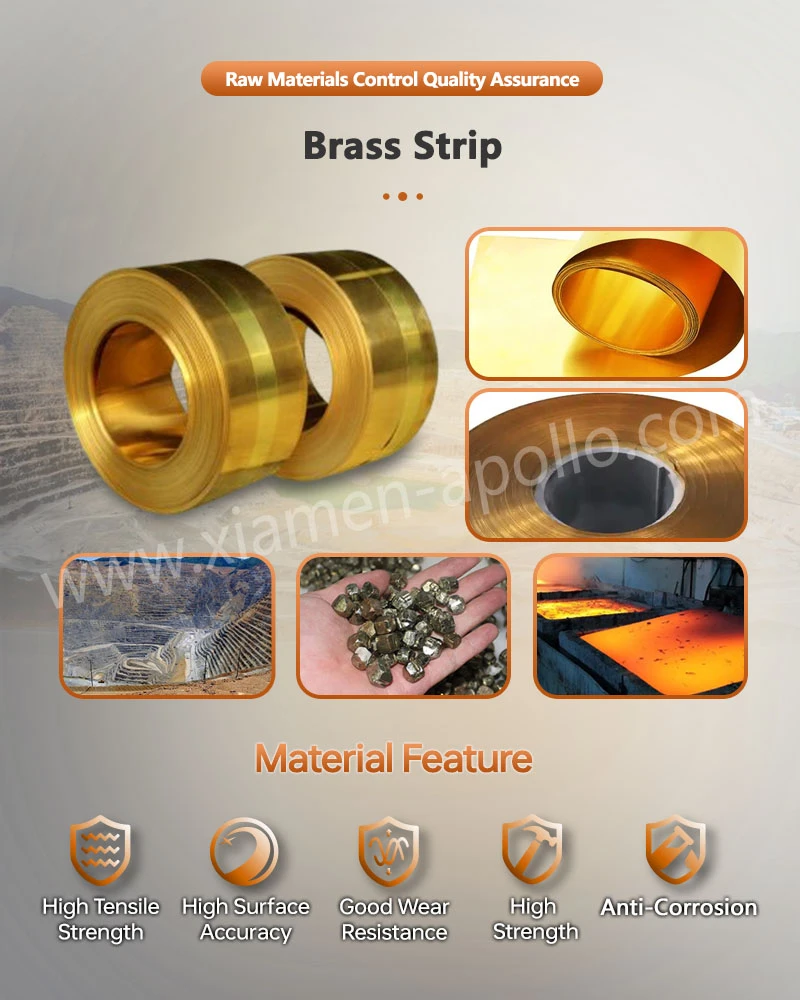
Copper and brass offer different balances of electrical conductivity, mechanical strength, formability, and machinability. The appropriate grade must be selected according to current-carrying requirements, forming severity, fastening loads, and operating temperature.
| Material family | General characteristics | Typical engineering considerations |
|---|---|---|
| C11000 / high-conductivity copper | High electrical conductivity and good thermal conductivity | Suitable where current carrying and heat dissipation dominate |
| C10200 / oxygen-free copper | High conductivity with controlled oxygen content | Consider where material chemistry and joining requirements are specified |
| C26000 brass | Good formability and useful machinability | Suitable for selected terminal and connector geometries where conductivity requirements permit |
| C36000 free-machining brass | Good machinability | Evaluate electrical conductivity, applicable regulations, and material composition before selection |
| C17200 beryllium copper | High strength and spring properties after appropriate heat treatment | More relevant to elastic contact or spring functions than bulk high-current conduction alone |
These grades are not interchangeable. The material specification should identify the alloy designation, temper, thickness or stock dimensions, applicable material standard, and any required conductivity or mechanical-property limits.
For copper terminals carrying substantial current, the design must also account for cross-sectional area, current density, joint resistance, ambient temperature, cooling conditions, and permissible temperature rise.
Download Contact Material Spec Sheet
Cost Reduction for High-Current Electrical Terminals: A Design-Based Example
High-current terminals often combine a conductive copper body with mounting features, fastening interfaces, and geometric requirements for connection to busbars, cables, or contact assemblies. Machining the entire component from solid stock may remove material that contributes little to its electrical or mechanical function.
A stamped preform followed by localized CNC machining can reduce unnecessary material removal and machining time. The actual savings depend on part geometry, material thickness, strip layout, machining allowance, cycle time, scrap rate, and tooling investment.
Identifying the Main Cost Drivers in a High-Current Terminal
Examine the cost structure at the feature level rather than treating the terminal as a single, undifferentiated component.
| Cost driver | Potential issue with full CNC machining | Hybrid process opportunity |
|---|---|---|
| Raw copper stock | Large starting stock may create substantial chips | Stamp the approximate terminal profile from suitable sheet stock |
| Material removal | Long machining cycles for non-critical contours | Reserve CNC operations for specified precision features |
| Threaded mounting points | Additional drilling and tapping time | Machine only required threaded interfaces |
| Outer profile | Repeated contour milling | Produce the profile through stamping where feasible |
| Part handling | Multiple setups may increase labor and variation | Use a defined stamping-to-machining transfer and locating method |
| Dimensional inspection | Excessive inspection of non-critical features | Apply drawing-based inspection plans with clear critical-to-quality characteristics |
| Scrap and rework | Machining defects or setup errors can scrap high-value material | Validate preform geometry, datum stability, and machining allowances before volume release |
Calculate material savings from actual mass and purchasing data. A theoretical reduction in removed volume does not necessarily equal the same percentage reduction in total manufacturing cost.
Electrical and Mechanical Validation Before Cost Approval
A lower manufacturing quotation is only useful if the finished terminal meets its electrical and mechanical requirements.
For high-current connections, validation should address:
- Electrical resistance: Measure the finished joint using a defined test method and controlled contact conditions.
- Temperature rise: Evaluate the terminal under specified current, ambient temperature, mounting configuration, and cooling conditions.
- Mechanical strength: Verify fastening torque, pull-out resistance, joint strength, or other drawing-defined requirements.
- Dimensional compliance: Check critical hole positions, mating surfaces, flatness, and terminal alignment.
- Surface condition: Confirm that burrs, plating defects, chips, or contamination do not compromise assembly.
- Environmental performance: Apply relevant temperature cycling, corrosion, vibration, or other qualification tests where required by the application.
IEC 60947 may be relevant to low-voltage switchgear and controlgear, depending on the product category. The applicable part of the standard and the customer's qualification requirements must be established before testing. A component-level test alone does not establish compliance of the complete electrical assembly.
When Hybrid Manufacturing Is Not the Right Choice
The combined route is not automatically the lowest-cost option.
It may be unsuitable when:
- Annual demand is too low to recover dedicated tooling investment.
- The terminal geometry requires extensive forming operations that create unacceptable distortion.
- The required CNC features are already simple and inexpensive to machine from standard stock.
- Material thickness or alloy condition makes the proposed stamping route impractical.
- Design changes occur frequently enough to create repeated die-modification costs.
- The finished component requires extensive post-machining correction or rework.
The manufacturing decision should be based on a quotation and process review using the released drawing, annual demand forecast, critical tolerances, material grade, and inspection plan.
OEM Sourcing from China: Evaluating Manufacturing and Quality Control
For an OEM or ODM purchasing team, sourcing complex electrical terminals involves more than comparing unit prices. Process integration, drawing control, material traceability, dimensional verification, and the management of manufacturing changes all affect the final cost and production risk.
A China-based electrical terminal manufacturer may offer integrated stamping and CNC machining, but the buyer should verify which operations are performed in-house, which are outsourced, and how responsibility for final inspection is allocated.
Manufacturing Capability Review for Custom Metal Stamping OEM Projects
A supplier assessment should connect equipment capability to the actual terminal drawing and expected production volume.
| Audit item | Evidence to request | Why it matters |
|---|---|---|
| Stamping capability | Press range, die type, material-thickness limits, process samples | Confirms that the preform can be produced with suitable repeatability |
| CNC capability | Machine configuration, workholding method, demonstrated feature tolerances | Confirms that secondary machining can meet drawing requirements |
| Tooling management | Die maintenance records, tool-life monitoring, revision history | Reduces the risk of dimensional drift and unplanned downtime |
| Material control | Mill certificates, alloy designation, temper, incoming inspection records | Establishes material identity and specified properties |
| Dimensional inspection | Calibration records, measurement equipment, inspection plans | Supports traceable verification of critical features |
| Process traceability | Lot identification, production records, nonconformance reports | Supports investigation of defects and containment of affected lots |
| Change management | Approved drawings, revision records, deviation authorization | Prevents unauthorized changes to materials or manufacturing processes |
| Outsourced operations | Approved subcontractor list, inspection responsibilities, transfer records | Clarifies accountability for external machining, plating, or finishing |
An ISO 9001 or IATF 16949 certificate should be checked for scope, validity, issuing body, and applicability to the manufacturing site and process. IATF 16949 is an automotive quality management system standard; it should not be treated as a universal requirement for every electrical terminal supplier.
Material Traceability and Compliance for Copper Electrical Terminals
Material traceability should connect each production lot to its material certificate, incoming inspection record, manufacturing batch, and final inspection results.
For copper and brass terminals, procurement specifications should define:
- Exact alloy and temper.
- Material standard and applicable revision.
- Electrical conductivity requirements, if specified.
- Mechanical properties relevant to forming or fastening.
- Material thickness and dimensional tolerances.
- Surface finish, plating, or corrosion requirements.
- Applicable RoHS and REACH obligations.
- Required records, retention periods, and lot-marking rules.
RoHS and REACH have different regulatory scopes and should be assessed against the specific product, substance restrictions, and applicable exemptions. A generic declaration does not replace verification of the materials and substances relevant to the purchased component.
ASTM B117 may be used as a salt-spray exposure practice when specified by the customer, but passing a salt-spray test does not independently establish the service life of a terminal in every operating environment.
Cost Transparency in an Electrical Terminal Supplier Quotation
A useful quotation separates costs that behave differently as production volume changes.
Request separate values for:
- Die design, manufacture, and validation.
- Unit material cost and the assumed material utilization.
- Stamping and secondary CNC machining.
- Deburring, plating, cleaning, and other finishing operations.
- Inspection and qualification testing.
- Packaging, transportation, and applicable export charges.
- Minimum order quantity (MOQ) and price breaks.
- Sample lead time and mass-production lead time.
- Tool ownership, storage, maintenance, and modification charges.
- Scrap assumptions, replacement policy, and nonconformance handling.
The quote should identify the drawing revision, annual volume assumption, packaging requirements, payment terms, and validity period. This makes it easier to compare a China manufacturer, an alternative supplier, or an existing factory using the same cost basis.
Sample Approval and Production Release
The first-article approval process should establish that the proposed manufacturing route can repeatedly produce the required geometry and material properties.
A practical sequence is:
- Review the drawing, material specification, critical-to-quality characteristics, and expected demand.
- Confirm the proposed stamping and CNC sequence, datum scheme, and machining allowance.
- Produce initial samples and inspect all designated critical features.
- Verify material certificates and required electrical or mechanical test results.
- Resolve nonconformances and document approved process changes.
- Release mass production only after the customer approves the agreed sample and documentation package.
- Maintain process and inspection records for subsequent production lots.
The required sample quantity and lead time depend on tooling complexity, material availability, test requirements, and the approval workflow. They should be agreed in writing rather than assumed from a generic supplier schedule.
Consult Our Electrical Engineers Today
Frequently Asked Questions
What tolerances can a supplier achieve when combining metal stamping and CNC machining?
Selected stamped features may achieve tolerances around ±0.02 mm, while selected CNC-machined features may achieve ±0.01 mm under suitable conditions.
How does Xiamen Apollo Electric Co., Ltd ensure material traceability and quality compliance?
All parts are manufactured in an IATF 16949 and ISO 9001 certified facility, utilizing strict lot-number tracking, chemical composition spectrometry, and automated optical inspection (AOI) to meet IEC 60947 and ASTM standards.
What is the typical prototype and production lead time for custom OEM metal components?
Standard prototype samples are delivered within 10 to 15 business days following engineering drawing approval, while mass production lead times range from 10 to 15 business days depending on order volume and tooling complexity.
contact us
Partner with our engineering team to evaluate your custom Electrical Metal Stamping and CNC machining requirements. Send your CAD drawings and technical specifications to our engineering division today for a comprehensive design-for-manufacturing (DFM) review and competitive cost-reduction proposal.