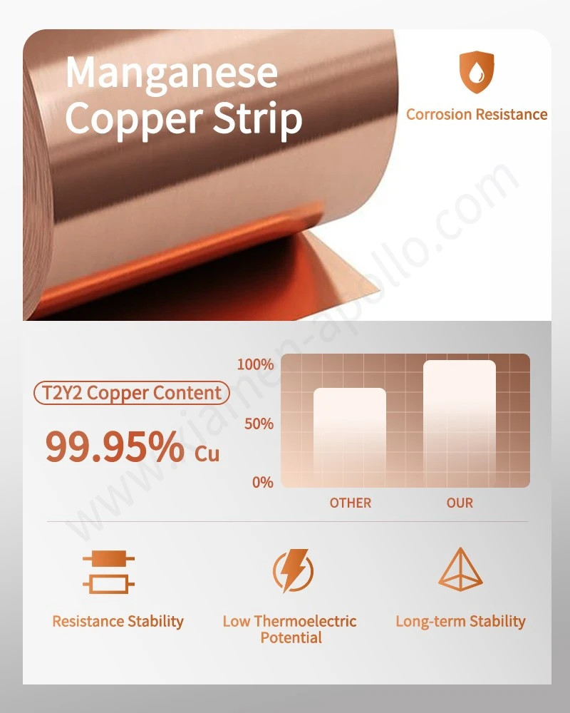
Manganin Copper Shunt Assemblies convert current into a measurable voltage drop through a calibrated low-resistance element, allowing smart meters and battery management systems (BMS) to calculate current from the measured voltage. Manganin provides a low temperature coefficient of resistance (TCR), while copper terminals reduce connection resistance and support current transfer. For precision current sensing, the design must control resistance tolerance, thermal drift, joint integrity, and measurement error across the specified operating range.
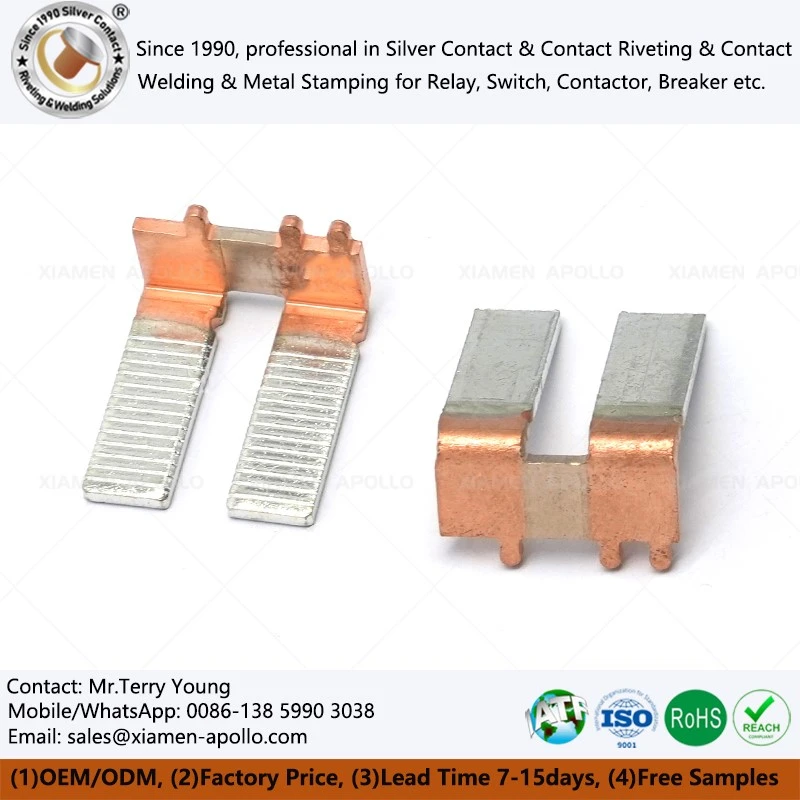
Manganin Alloy Properties and TCR Control for Precision Current Sensing
Why Manganin Is Used in Low-Resistance Shunt Resistors
Manganin is a copper-based resistance alloy commonly containing copper, manganese, and nickel. Its composition and heat treatment are selected to achieve stable electrical resistance and a low TCR over the intended temperature range.
Unlike a copper conductor, whose resistance changes noticeably with temperature, a properly processed manganin element can maintain a relatively stable resistance as operating temperature varies. This characteristic makes manganin suitable for precision shunt resistors used in energy metering, battery monitoring, and industrial current measurement.
A practical design target for a precision manganin shunt may be a TCR below 50 ppm/°C. This is a specification target rather than a universal property of every manganin grade; actual performance depends on alloy composition, processing, geometry, and temperature range.
Key Electrical Parameters for Smart Meter Shunt Resistors
| Parameter | Engineering consideration | Example design target |
|---|---|---|
| Resistance value | Determines voltage output at rated current | 50–500 μΩ, depending on circuit design |
| TCR | Controls temperature-induced resistance drift | Below 50 ppm/°C |
| Initial resistance tolerance | Determines calibration accuracy | ±0.5% or tighter, if required |
| Rated current | Determines operating voltage drop and heat generation | Defined by the meter or BMS design |
| Resistance stability | Indicates drift after thermal and electrical exposure | Established through application-specific testing |
| Joint resistance | Adds error and local heat at the copper–manganin interface | Controlled through weld design and validation |
| Insulation and clearance | Relevant to the complete assembly and its installation | Defined by the applicable product standard |
These values are example design targets, not guaranteed specifications for all assemblies. Final acceptance limits should be agreed upon in the component drawing and electrical test plan.
TCR Verification and Resistance Stability Testing
A manganin copper shunt supplier should define how TCR is measured rather than relying on a nominal alloy designation. A suitable verification plan includes:
- Four-wire Kelvin measurement to reduce lead and contact resistance errors.
- Resistance measurements at defined temperature points after thermal stabilization.
- Controlled measurement current to limit self-heating.
- Resistance comparison before and after thermal cycling or application-specific endurance testing.
- Traceable records linking alloy batches, component lots, and test results.
The temperature range, dwell time, current, and acceptance limits should match the component specification. A single room-temperature resistance measurement cannot establish TCR or long-term stability.
Electron Beam Welding of Manganin and Copper Terminals
Why the Copper–Manganin Joint Requires Process Control
Manganin and copper serve different electrical functions within the same shunt assembly. Manganin establishes the calibrated resistance, while copper provides a low-resistance connection to the circuit.
The joint is a potential source of measurement error. Excessive weld penetration, an inconsistent fusion zone, thermal damage to the resistance element, or geometric variation can change the effective resistance of the assembly.
Electron beam welding (EBW) uses a concentrated electron beam to deliver energy into a localized region. When performed under vacuum, it can produce a narrow weld with limited surrounding heat input. However, the process window must be developed for the specific alloy combination, joint geometry, and component dimensions.
EBW Process Variables and Quality Controls
| Process variable | Potential failure mode | Recommended control |
|---|---|---|
| Beam power | Incomplete fusion or excessive penetration | Establish a validated power window |
| Welding speed | Variable weld depth and heat input | Lock speed parameters after process qualification |
| Focus position | Irregular fusion-zone geometry | Verify focus using representative test coupons |
| Joint gap and alignment | Incomplete bonding or asymmetric welds | Control fixture position and component tolerances |
| Vacuum condition | Beam instability or contamination-related defects | Monitor equipment vacuum parameters |
| Component cleanliness | Porosity, inclusions, or inconsistent bonding | Define cleaning and handling requirements |
| Thermal input | Resistance-element drift or localized distortion | Validate weld sequencing and heat effects |
| Weld geometry | Current concentration or unstable joint resistance | Inspect weld cross-sections and electrical results |
The numerical limits for these variables should be established through process development and recorded in the approved welding procedure. Universal beam-power or welding-speed settings are not appropriate because the required energy input depends on material thickness, joint design, and equipment configuration.
| Comparison factor | Electron beam welding (EBW) | Resistance welding | Brazing |
|---|---|---|---|
| Heat generation | Concentrated electron-beam energy | Electrical resistance at the joint | Heat supplied to melt filler metal |
| Atmosphere | Usually vacuum for EBW | Typically ambient or controlled atmosphere | Air, protective atmosphere, or vacuum, depending on process |
| Joint formation | Fusion of base materials | Localized fusion or solid-state bonding, depending on process | Filler metal bonds the components |
| Heat-affected region | Can be narrow with suitable parameters | Localized, depending on electrode and current settings | Depends on heating cycle and joint design |
| Main control concern | Penetration, fusion geometry, and thermal impact | Electrode force, current, time, and contact condition | Filler flow, wetting, joint clearance, and temperature |
| Application suitability | Precision joints requiring concentrated energy input | High-volume joining with suitable joint geometry | Assemblies requiring filler-assisted joining |
No joining process is automatically superior for every shunt design. The selection should account for the required joint resistance, production volume, component geometry, cost, inspection method, and resistance stability after joining.
Weld Validation: Electrical Resistance and Cross-Section Inspection
A weld that looks acceptable externally may still contain incomplete fusion or a nonuniform interface. Validation should combine electrical and metallurgical checks.
Recommended verification methods include:
- Four-wire resistance measurement of the completed shunt.
- Weld cross-section analysis to examine penetration and fusion continuity.
- Pull, shear, or other mechanical testing where the joint design requires it.
- Resistance comparison before and after thermal cycling.
- Dimensional inspection of the current path and weld position.
- Failure analysis for units showing abnormal resistance drift or local heating.
Acceptance criteria should be established from the drawing, product risk assessment, and application requirements. IEC 60947 may be relevant to certain low-voltage switching and control equipment, while smart meters and automotive battery systems require evaluation against their respective product and application standards.
Download Contact Material Spec Sheet

Current Sensing Design for Smart Meters and Battery Management Systems
Smart Meter Shunt Resistors: Resistance Stability Over Time
Smart meters measure electrical energy by sampling voltage and current and processing the signals through a metering circuit. In a shunt-based current channel, the resistance value directly affects the voltage presented to the measurement front end.
The shunt design must balance three variables:
- Voltage signal: A higher resistance produces a larger voltage signal at a given current but also increases power dissipation.
- Self-heating: Power loss follows (P=I^2R). Excessive temperature rise can affect resistance stability and nearby components.
- Measurement burden: The voltage drop across the shunt reduces the voltage available to the connected circuit and must remain within the design budget.
- For example, a 100 μΩ shunt carrying 100 A produces a 10 mV drop and dissipates 1 W. These figures are illustrative and do not establish the rated current of a particular product.
Meter designs should consider continuous current, overload duration, ambient temperature, PCB layout, terminal connection resistance, and the metering IC's input range. Calibration at one current and one temperature may not adequately characterize performance across the full operating envelope.
BMS Current Sensing: Pulse Loads and Thermal Cycling
A battery management system uses current measurements to support charge and discharge monitoring, overcurrent protection, and battery-state estimation. The shunt may experience continuous current, short-duration peaks, regenerative current, and repeated thermal cycles.
The resistance element and copper terminals must be designed for the expected electrical and mechanical loads. Key verification points include:
Continuous current and peak-current duration.
- Resistance drift under repeated load cycles.
- Temperature rise at the manganin element and welded interfaces.
- Mechanical integrity under vibration and thermal expansion.
- Measurement accuracy in both charging and discharging directions, where applicable.
- Compatibility with the selected current-sensing amplifier and ADC.
For high-current battery systems, the current path and the voltage-sensing path should be considered separately. A Kelvin connection takes the measurement from defined sense points to reduce errors caused by voltage drops in the main current terminals. Incorrect sense-point placement can undermine the accuracy gained from a low-TCR alloy.
Manganin Shunt Versus Copper-Only Current Sensing
| Characteristic | Manganin copper shunt | Copper‑only conductor |
|---|---|---|
| Primary function | Provides a calibrated low‑resistance measurement element | Transfers current with low conductor resistance |
| Temperature coefficient | Designed for low TCR within a specified range | Copper resistance increases significantly with temperature |
| Voltage signal | Determined by the calibrated shunt resistance | Often too small or temperature‑dependent for precise measurement without additional calibration |
| Thermal design | Must control element self‑heating and joint heating | Must control conductor heating and connection losses |
| Typical role | Precision current measurement | Busbar or power interconnection |
| Calibration needs | Resistance and TCR characterization | Depends on sensing architecture and compensation method |
Copper alone can be used for current sensing in certain architectures, including systems that measure magnetic fields or compensate for conductor resistance. However, for a conventional resistive shunt requiring a stable, calibrated voltage-to-current relationship, manganin offers a more suitable resistance element.
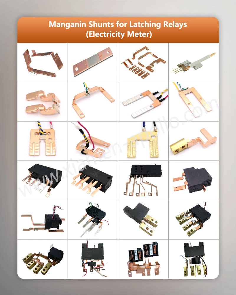
Manufacturing Quality, Traceability, and Production Inspection
Material and Dimensional Controls for Manganin Copper Shunt Assemblies
Stable current sensing requires consistent material properties and repeatable component geometry. Variations in manganin composition, element dimensions, copper terminal thickness, or weld position can affect both resistance and heat distribution.
A manufacturing control plan should cover:
- Alloy grade and incoming material traceability.
- Manganin element dimensions and copper terminal geometry.
- Resistance measurement before and after joining, where defined.
- Weld position, penetration, and interface integrity.
- Final resistance, dimensional, and visual inspection.
- Lot identification and nonconformance records.
The applicable dimensional tolerances and electrical acceptance limits should be specified on the approved drawing. A tolerance such as ±0.01 mm should only be used when it is appropriate for the actual part geometry and manufacturing process.
Production Testing and Measurement Equipment
| Inspection item | Suitable method | Purpose |
|---|---|---|
| Initial resistance | Four‑wire Kelvin measurement | Confirm the specified resistance value |
| TCR | Resistance measurements at controlled temperatures | Quantify temperature‑dependent drift |
| Weld integrity | Metallographic cross‑section and suitable mechanical tests | Verify joint formation |
| Dimensional conformity | Calibrated measuring instruments or optical inspection | Check component geometry and fit |
| Temperature rise | Controlled current loading with temperature measurement | Verify thermal behavior |
| Resistance stability | Before‑and‑after electrical measurements under a defined test profile | Detect changes caused by environmental or electrical stress |
| Lot traceability | Material certificates, production records and inspection reports | Link the delivered batch to its material and process history |
Testing frequency should reflect production volume, process capability, component criticality, and customer requirements. First-article inspection, periodic verification, and statistical process monitoring can be combined where appropriate.
ISO 9001 provides a quality management framework. IATF 16949 applies to organizations and supply chains within its automotive scope; it should not be claimed as a certification unless the relevant manufacturing site holds valid certification. RoHS and REACH compliance should be supported by applicable material declarations and supply-chain documentation.
| Failure mode | Electrical consequence | Prevention or detection |
|---|---|---|
| Incorrect manganin resistance | Calibration offset | Incoming and final resistance verification |
| Excessive weld penetration | Changes to the effective resistance element | Weld procedure qualification and cross‑section inspection |
| Incomplete fusion | Unstable joint resistance and localized heating | Process monitoring and joint validation |
| Poor Kelvin sense‑point placement | Additional voltage measurement error | Controlled drawing and PCB layout review |
| Excessive self‑heating | Resistance drift and thermal stress | Current‑load and temperature‑rise testing |
| Material or geometry variation | Lot‑to‑lot resistance variation | Material traceability and dimensional process control |
| Oxidation or contamination at interfaces | Increased connection resistance in susceptible designs | Cleaning control and suitable surface protection |
Failure analysis should distinguish between drift in the manganin element, resistance changes at the copper joint, and errors introduced by the measurement circuit. Treating every measurement deviation as an alloy problem can lead to unnecessary material changes while leaving the actual failure mechanism unresolved.
Consult Our Electrical Engineers Today
Frequently Asked Questions
1. How is the TCR of a manganin copper shunt resistor measured?
Measure resistance using a four-wire Kelvin method at two or more controlled temperatures after thermal stabilization. Calculate TCR from the resistance change and temperature difference over the specified range. The test current must limit self-heating, and the report should identify measurement uncertainty and acceptance criteria.
2. What information is required to obtain a quotation for a custom smart meter shunt resistor?
Provide the nominal resistance, tolerance, TCR, rated and overload currents, temperature range, terminal dimensions, joining requirements, annual demand, and applicable inspection standards. A drawing or 3D model helps establish manufacturability, tooling requirements, prototype scope, and production pricing.
3. How can an OEM verify material traceability and weld quality for a manganin copper shunt assembly?
Request material batch records, component lot identification, resistance test results, and weld inspection reports. Where specified, review metallographic cross-sections and thermal or electrical endurance data. ISO 9001 or IATF 16949 certification should be verified against the actual manufacturing site's certification scope.
contact us
Submit your resistance target, TCR limit, current profile, and component drawing for a manufacturing feasibility review of the Manganin Copper Shunt Assemblies. Factory engineering teams can assess manganin and copper material selection, EBW joint design, resistance testing, and production inspection requirements before prototype approval and volume procurement.