Progressive Die Stamping combines piercing, blanking, bending and in-die riveting in a continuous press cycle, reducing intermediate handling and controlling the positional relationships between features. For electrical components used in relays, circuit breakers and contactors, die accuracy, strip-feed stability, contact attachment and burr direction directly affect assembly fit, electrical contact alignment and production yield. A qualified progressive die stamping supplier must validate these variables against the component drawing, material specification and required production volume before releasing the tooling.
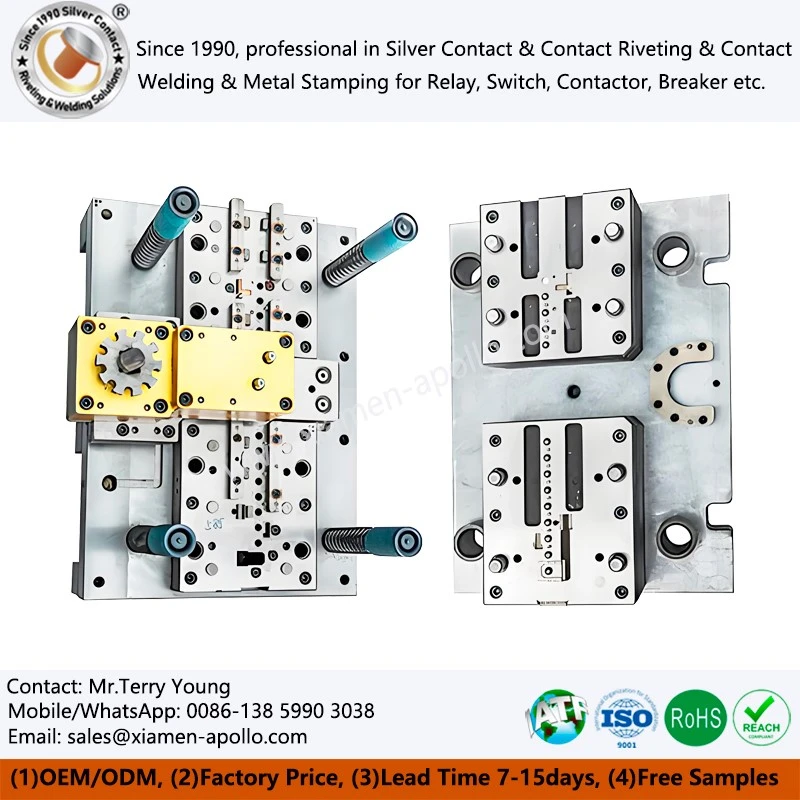
Progressive Die Station Layout for ±0.02 mm Electrical Stamping Accuracy
Establishing a Datum System for Precision Stamping Mold Design
The strip layout determines how each feature is formed, located and supported throughout the press cycle. Datum selection should account for strip movement, material springback, pilot-hole accuracy and the final assembly reference surfaces.
For relay moving springs, contact carriers and switch terminals, the datum system should distinguish between functional dimensions and non-critical cut edges. A hole used to locate a silver contact, for example, may require tighter positional control than an external profile that does not influence assembly.
Key design checks include:
- Define primary and secondary datums from the functional assembly drawing and GD&T requirements.
- Establish pilot-hole locations before precision piercing and bending stations.
- Evaluate strip-carrier stiffness to prevent lateral movement during forming.
- Compensate for material springback using measured trial results rather than nominal CAD geometry alone.
Specify dimensional tolerances according to feature function; ±0.02 mm may be appropriate for selected features, but it is not a universal capability for every stamped part.
Sequencing Piercing, Bending and Blanking Operations
A progressive die should distribute forming loads across stations to limit strip distortion and reduce dimensional interaction between operations. Piercing before bending is generally preferable when the hole must remain accurately positioned relative to the flat datum, although the sequence depends on geometry and tool accessibility.
The final cutoff station must maintain adequate support until the component is separated from the carrier. Insufficient support can cause twist, edge deformation or inconsistent flatness, especially in thin copper-alloy springs.
| Design variable | Engineering consideration | Verification method |
|---|---|---|
| Punch-to-die clearance | Set according to material grade, thickness, ductility and required edge quality | Sectioned edge inspection and burr measurement |
| Pilot-hole accuracy | Controls strip registration between stations | Optical measurement or CMM |
| Bending allowance | Accounts for thickness, bend radius and springback | First-article dimensional inspection |
| Carrier width | Provides stiffness during feeding and forming | Strip-trial observation and dimensional checks |
| Cutoff support | Limits twist and deformation during separation | Flatness and profile inspection |
Clearance must be established from the material and thickness rather than copied from an unrelated tool. Excessive clearance can increase burr height and rollover; insufficient clearance can increase cutting force, accelerate edge wear and raise the risk of punch damage.
Managing Burr Direction and Functional Contact Surfaces
Burr orientation is an electrical and mechanical design variable. On a relay spring or switch terminal, a burr near the contact interface can interfere with contact seating, alter local stress or create an unwanted edge condition during assembly.
The drawing should identify permitted burr locations and maximum burr height. Where the part carries a riveted silver contact, the die designer should also check whether the burr interferes with the rivet head, contact seating surface or downstream assembly fixture.
For components specified under an IEC 60947 application, dimensional inspection alone does not establish switching compliance. The finished component must still be evaluated within the relevant electrical assembly and its intended operating conditions.
Validating Strip Layout Before Tool Manufacture
A strip-layout review should be completed before cutting the die plates. The review should include material utilization, feed pitch, station loading, carrier integrity, slug discharge and access for maintenance.
The engineering team should confirm the following before release:
- The strip remains stable through every forming and cutting station.
- Critical dimensions can be measured without destructive disassembly of the tool.
- Scrap and slugs can leave the die without accumulating near the punches.
- Sensors and maintenance access points do not compromise tool rigidity.
- The proposed cycle rate is supported by press capacity, material behavior and part geometry.
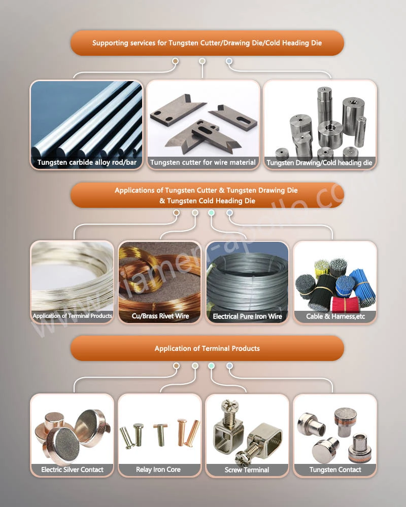
Carbide Tool Inserts and Die Life Under High-Volume Production
Selecting Carbide Grades for Punches and Wear Inserts
Cemented carbide inserts can reduce wear in high-load cutting locations because of their hardness and compressive strength. However, carbide grade selection must balance wear resistance against fracture toughness, particularly when punching thin, high-strength copper alloys or processing strip with variable hardness.
The tooling specification should identify the intended function of each insert rather than treating every die component as a carbide application. Punches, cutting inserts, forming tools and guide elements experience different combinations of impact, sliding wear and bending load.
| Tool material or feature | Typical engineering role | Main selection concern |
|---|---|---|
| Cemented carbide insert | High-wear piercing and blanking locations | Grade-specific fracture toughness and edge stability |
| Hardened tool steel | Punches, die blocks and forming elements | Wear resistance, heat treatment and toughness |
| Precision guide components | Maintain alignment between punch and die | Clearance, lubrication and resistance to wear |
| Replaceable cutting insert | Simplify restoration of worn cutting geometry | Repeatable seating and dimensional consistency |
A carbide insert does not automatically guarantee millions of strokes. Tool life depends on carbide grade, insert geometry, press alignment, strip hardness, lubrication, clearance, slug evacuation and maintenance practices. A million-stroke target should be treated as a validation objective supported by documented production trials, not as an unconditional material property.
Controlling Punch Wear and Cutting Clearance
Punch wear gradually changes the cutting edge radius and the force required to separate material. The resulting changes may appear as increased burr height, dimensional drift, fractured edges or unstable slug release.
For high-volume electrical stamping, maintenance criteria should be based on measurable indicators:
- Burr height and edge rollover at defined inspection intervals.
- Critical hole dimensions and positional tolerances.
- Press tonnage trends or abnormal load signatures.
- Tool-edge condition under magnification.
- Slug evacuation performance and evidence of slug pulling.
The inspection frequency should reflect the material, tool geometry, press speed and observed wear rate. A fixed stroke interval is useful as a starting point, but it should be revised using actual process data.
Designing Replaceable Inserts for Repeatable Maintenance
Replaceable inserts can reduce downtime when wear is concentrated in specific cutting stations. The insert pocket, locating faces and fastening arrangement must return the cutting geometry to its intended position after replacement.
The die drawing should define insert identification, orientation, seating requirements and the inspection dimensions needed after maintenance. Where several stations control one functional dimension, replacement procedures must preserve their relative positions rather than merely restoring each punch.
A custom stamping die maker should also maintain a record of insert changes, sharpening operations, dimensional corrections and verified stroke counts. These records help distinguish normal wear from misalignment, material variation or incorrect setup.
Validating Tool Life Through Production Trials
A tooling acceptance trial should evaluate both dimensional stability and production continuity. The initial sample may pass inspection while later output shows drift caused by wear, thermal effects, lubricant changes or unstable feeding.
A suitable validation plan should record:
- Initial first-article dimensions.
- Dimensional results at predefined stroke intervals.
- Burr height and edge condition.
- Unplanned stops and their causes.
- Tool maintenance actions and post-maintenance results.
Where the customer requires a defined tool-life target, the acceptance criteria should specify the material grade, strip thickness, operating speed, maintenance conditions and allowable part defects.
Download Contact Material Spec Sheet
In-Die Sensors and Feed Error Prevention in Progressive Stamping
Detecting Misfeeds Before Tool Damage Occurs
A feed error can shift the strip away from its intended station position. If the press continues cycling, a punch may strike the wrong area, a pilot may enter an incorrectly positioned hole, or a formed component may be crushed between tooling surfaces.
Misfeed detection should be designed around the failure mode. Common monitoring points include strip presence, feed position, pilot-hole engagement, part presence and slug discharge.
The sensor arrangement must account for the press cycle and the available stopping response. Detecting an error is insufficient if the press cannot stop before the next damaging tool engagement.
Selecting Sensors for Specific Failure Modes
| Sensor or monitoring method | Intended detection | Design limitation |
|---|---|---|
| Feed-position sensor | Strip advance outside the permitted range | Must distinguish normal feed motion from an actual fault |
| Pilot or misfeed detector | Incorrect strip registration before tool closure | Requires suitable sensing geometry and cycle timing |
| Part-presence sensor | Missing or retained component at a defined station | May be affected by oil, debris or reflective surfaces |
| Slug or scrap monitoring | Blocked discharge or abnormal slug behavior | Detection depends on scrap shape and discharge design |
The control specification should define the detection point, response time, stop logic, reset procedure and fault-recording requirements. Safety-related stopping functions must be designed and validated in accordance with the applicable machinery safety requirements; an ordinary process sensor should not be assumed to provide a safety-rated function.
Integrating Sensors With the Press Control System
Sensor installation requires a complete view of the press cycle. The designer should verify that the controller can distinguish startup conditions, normal feed movement, missing material and an actual misfeed.
A practical validation sequence includes simulated faults under controlled conditions. Test cases should cover strip interruption, abnormal feed pitch, missing components, blocked scrap discharge and sensor disconnection where relevant.
The results should confirm that each defined fault produces the intended machine response before tooling is approved for production.
Reducing False Stops Without Hiding Process Defects
Excessive false stops reduce output and may encourage operators to bypass detection. Insufficient sensitivity can allow tool damage and defective parts to continue through the process.
Sensor thresholds should therefore be established using representative material, production speed, lubricant conditions and normal strip variation. Every adjustment should be recorded and verified against the original failure mode.
For automotive electrical components subject to customer quality requirements, sensor checks and fault responses can be incorporated into the process control plan and production records aligned with IATF 16949 requirements where applicable.
In-Die Riveting for Electrical Contacts and Copper-Alloy Carriers
Coordinating Rivet Feeding, Positioning and Staking
In-die riveting combines rivet feeding, component positioning and mechanical joining within the progressive stamping sequence. It can reduce separate handling operations, but only if the carrier strip, rivet orientation, receiving hole and staking geometry remain stable throughout the cycle.
For relay contacts and switch terminals, rivet-head position and attachment integrity influence assembly fit and contact alignment. The die design must also provide a reliable method of detecting missing, reversed or incorrectly seated rivets.
Controlling Rivet Geometry and Joint Integrity
The joining process should be qualified against the actual rivet material, shank diameter, receiving-hole geometry, carrier thickness and required joint strength. A universal staking force or shear-strength threshold should not be specified without supporting test data.
Inspection should consider head diameter, head height, shank deformation, joint pull-out or shear performance, and damage to the surrounding strip. The selected test method must match the joint design and intended load direction.
For bimetal silver contacts, the silver contact material and copper-based carrier perform different functions. The contact material must satisfy the electrical and switching requirements, while the carrier must provide the specified mechanical support and current path.
Preventing Contact Misalignment and Surface Damage
Contact alignment errors can originate from an inaccurately located hole, inconsistent rivet feed, strip movement or an unstable staking station. The die should locate the carrier from a repeatable datum and support the contact area during joining.
Inspection should verify the contact center position relative to the assembly datum, head height, seating condition and visible surface damage. Where contact resistance is a product requirement, electrical verification should be performed using a defined measurement method and controlled test conditions.
Verifying Riveted Components Against IEC 60947 Requirements
IEC 60947 applies to relevant low-voltage switchgear and controlgear equipment, but compliance cannot be established by rivet geometry alone. The complete component or assembly must meet the applicable electrical, mechanical and environmental requirements for its intended category.
For production quality, the control plan should connect drawing characteristics to inspection methods, sampling frequency, reaction plans and traceable records. Material declarations under RoHS and REACH should also be supported by the relevant supplier documentation when required by the purchasing specification.
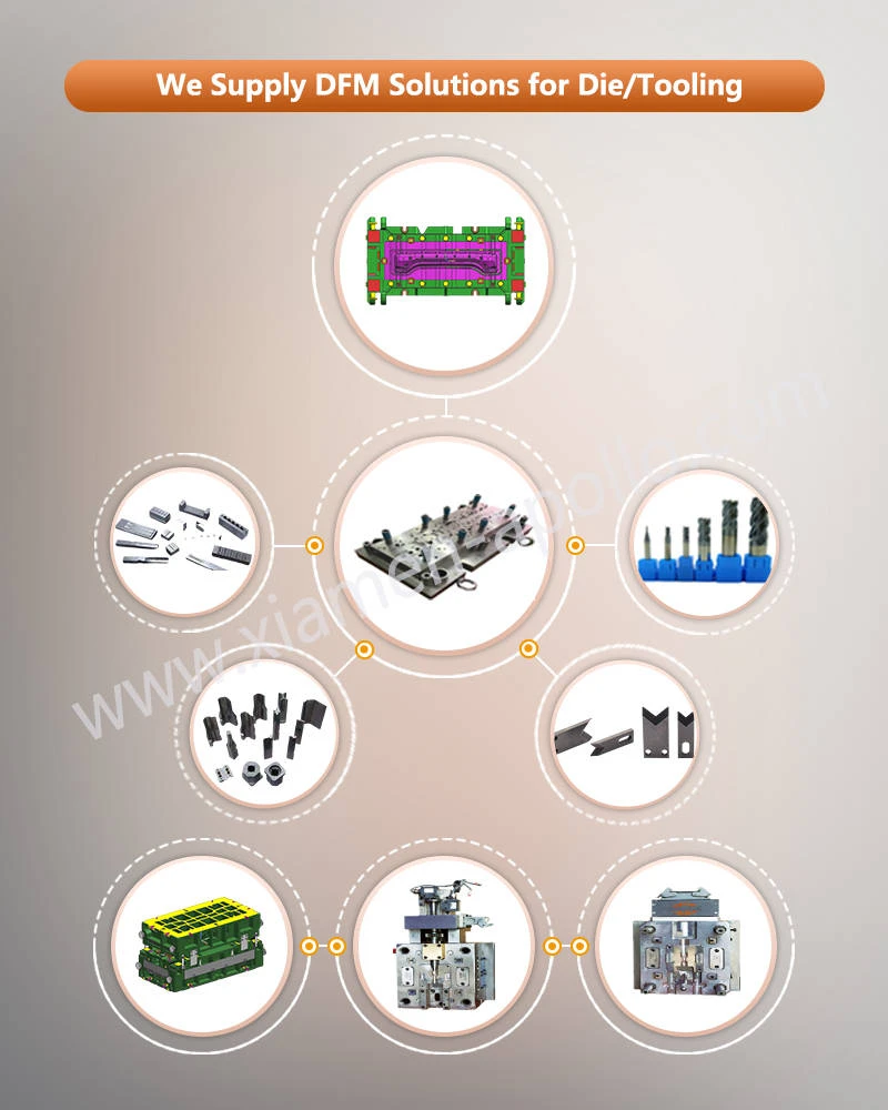
In-House Toolroom Maintenance and Production Traceability
Reducing Tool Repair Delays With an In-House Toolroom
An in-house toolroom can shorten the feedback loop between production, inspection and die correction. When a dimensional trend or burr defect appears, the tooling team can inspect the affected station, identify the likely wear mechanism and implement a controlled correction without relying entirely on an external repair schedule.
The benefit depends on available equipment, technician capability, spare-part availability and documented maintenance procedures. The presence of an in-house toolroom alone does not prove that every repair can be completed immediately.
Managing Preventive Maintenance and Die History
A progressive die maintenance record should identify the tool number, station, insert specification, maintenance date, stroke count, measured condition and corrective action.
Recommended records include:
- Tool setup and first-article approval.
- Punch and die clearance verification.
- Insert sharpening and replacement history.
- Sensor checks and misfeed incidents.
- Dimensional results before and after repair.
- Release approval following maintenance.
These records support trend analysis and help the quality team distinguish tool wear from changes in raw material, press setup or operator practice.
Connecting Material Traceability With IATF 16949 Quality Planning
Electrical stamping performance depends on incoming material properties as well as die condition. Copper alloys with different temper, thickness or mechanical properties can produce different springback, cutting loads and burr behavior even when the nominal grade is unchanged.
Where required by the customer, traceability should connect the incoming material batch to production orders, inspection records and finished-part lots. The quality plan should identify material certificates, drawing revisions, approved process parameters and disposition records for nonconforming parts.
IATF 16949 provides a quality management framework for automotive production and relevant service parts. Certification status must be verified for the actual manufacturing site and applicable scope; it should not be inferred from a supplier's general capability statement.
Establishing Production Release Criteria for Repeatable Output
Before a production order is released, the manufacturer and customer should agree on critical dimensions, inspection methods, sampling plans, material requirements and change-control procedures.
A controlled production release should establish:
- Approved drawing and revision status.
- Verified raw-material grade and thickness.
- First-article dimensional acceptance.
- Confirmed sensor response and press settings.
- Defined tool maintenance and inspection intervals.
- Traceable records for production and nonconforming material.
Consult Our Electrical Engineers Today
Frequently Asked Questions
1. How can a buyer verify the service life of a progressive stamping die?
Request production-trial records showing stroke count, material grade and thickness, press speed, maintenance intervals, burr measurements and dimensional results. Confirm the tool-life acceptance conditions and clarify whether the quoted life includes sharpening, insert replacement or other scheduled maintenance.
2. What information is required to obtain a quotation from a custom stamping die maker in China?
Provide the 2D drawing, 3D model if available, material grade and thickness, annual demand, target cycle rate, critical tolerances and required joining operations. Include contact-rivet specifications, inspection requirements and sample-validation expectations where applicable.
3. How are stamped electrical parts traced to material batches under IATF 16949 requirements?
Traceability is established through controlled material identification, production-order records, inspection results and finished-lot identification according to applicable customer and quality-system requirements. Buyers should confirm the required traceability level and verify the manufacturing site's certification scope.
contact us
Request a technical review of your next Progressive Die Stamping project now, including die layout, carbide inserts, in-die riveting and production validation, to establish a documented route to repeatable electrical stamping output.