Thermostat contact assemblies must maintain a defined switching temperature, stable contact resistance and repeatable mechanical separation across repeated thermal cycles. Contact geometry, silver-alloy selection, rivet or weld integrity, and the operating clearance between the contact pair and bimetal element determine whether a thermal protector opens and resets within its specified limits. For OEM production, these variables require measurable acceptance criteria rather than visual inspection alone.

Switching Response and Contact Separation in Thermal Protectors
How Contact Assemblies Affect Thermal Switching
A thermal overload protector converts temperature-induced movement of a bimetal element into mechanical contact separation. As the bimetal disc or strip reaches its calibrated transition temperature, the mechanism changes position and interrupts the electrical circuit. During cooling, the element returns toward its original geometry and restores contact when the design reset conditions are met.
The contact assembly must accommodate three simultaneous requirements:
- Electrical continuity: Contact resistance must remain within the product specification throughout the operating life.
- Mechanical response: The contact interface must separate without excessive friction, delayed release or interference from the surrounding structure.
- Switching stability: The contact pair must resist welding, excessive arc erosion and permanent deformation under the specified current and load type.
A response time measured in milliseconds cannot be guaranteed by contact geometry alone. Thermal mass, bimetal properties, heater configuration, mounting conditions, ambient temperature and current loading all influence the complete protector's response. The contact assembly supplier should therefore distinguish component-level measurements from finished-device switching tests.
Electrical Load and Contact Material Selection
Silver-based contact materials are commonly considered for thermal protectors because of their electrical conductivity and switching characteristics. The correct grade depends on the actual current, voltage, inductive content, switching frequency and expected electrical endurance.
| Contact material | Engineering characteristics | Selection considerations |
|---|---|---|
| AgNi | Silver-nickel alloy with good electrical conductivity and resistance to material transfer in many switching applications | Evaluate arc erosion and contact resistance under the actual load |
| AgSnO₂ | Silver-tin oxide composite with good resistance to welding under suitable switching conditions | Verify contact force, temperature rise and endurance for the specific circuit |
| Fine silver (Ag 99.99%) | High electrical conductivity and low bulk resistivity | Evaluate welding tendency and material transfer under switching arcs |
| Silver-plated copper | Conductive copper substrate with a silver surface layer | Confirm plating thickness, adhesion, porosity and wear exposure |
No contact material should be selected solely by comparing nominal conductivity. AgSnO₂ and AgNi behave differently under different current waveforms, contact forces and arc durations. Material selection should be validated against the finished protector's electrical endurance requirements and applicable product specifications, including IEC 60947 where relevant to the device category.
Engineering Variables for Repeatable Switching
The following parameters should be recorded during development and production qualification:
- Initial and stabilized contact resistance, measured in mΩ using a defined test current.
- Contact force and contact overtravel, measured in N and mm.
- Opening temperature and reset temperature, measured under a documented heating and cooling profile.
- Contact gap after opening, measured in mm at the specified operating condition.
- Temperature rise at the rated electrical load, measured in °C.
- Electrical endurance, recorded as completed switching cycles under a defined load.
A thermal protector that passes a room-temperature continuity test may still fail under load because of contact welding, local heating or insufficient opening clearance. Qualification must include the relevant thermal and electrical operating conditions.

Contact Geometry: Flat, Spherical and Crown Profiles
Flat Contact Surfaces for Defined Contact Interfaces
Flat contacts provide a straightforward interface for designs requiring a specified contact footprint and controlled mounting height. Their performance depends on surface flatness, parallelism, burr control and the alignment of the mating contact.
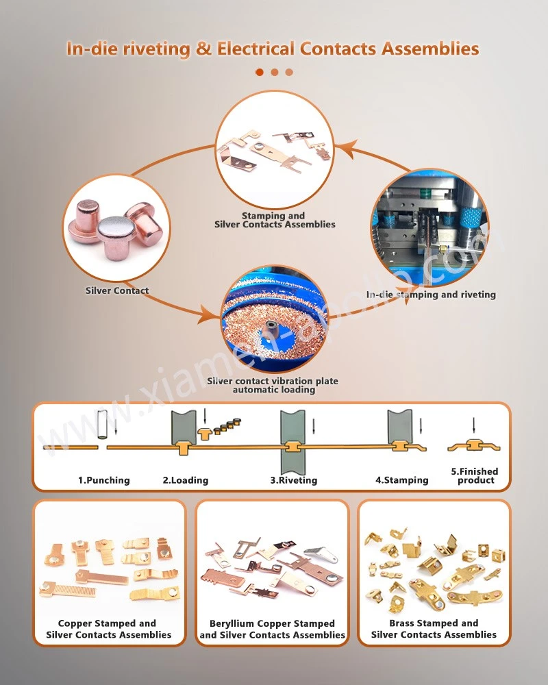
For stamped contact carriers, progressive die stamping can establish the overall outline and mounting features. Subsequent riveting or welding must not introduce excessive distortion that changes the contact plane.
Flat geometry should be evaluated for:
- Contact-face flatness and parallelism, specified in mm.
- Contact diameter and usable contact area, specified in mm.
- Burr height and edge condition after stamping.
- Contact alignment relative to the bimetal element.
- Surface condition after plating, riveting or welding.
A larger nominal contact face does not automatically provide a lower operating resistance. Actual contact resistance also depends on contact force, surface films, roughness and material deformation under load.
Spherical and Crown Contacts for Controlled Engagement
Spherical and crown-shaped contact faces concentrate the initial mechanical engagement over a smaller area than a fully flat interface. Under suitable contact force, local deformation can establish a stable conducting area while accommodating limited angular or positional variation.
These profiles require particular attention to crown height, radius, concentricity and wear. Excessive curvature can increase local stress and accelerate deformation; insufficient curvature can remove the intended engagement advantage.
| Geometry | Main design variable | Potential benefit | Main risk |
|---|---|---|---|
| Flat | Flatness and parallelism | Defined interface and straightforward dimensional inspection | Edge contact caused by misalignment |
| Spherical | Radius and apex position | Localized initial engagement | High local stress and wear |
| Crown | Crown height and profile symmetry | Controlled engagement with some alignment tolerance | Uneven wear or inconsistent contact force |
The final profile should be chosen from the protector's motion path, contact force, electrical load and dimensional stack-up. Geometry alone does not establish a guaranteed switching life.
Dimensional Tolerances and Functional Clearance
The bimetal element, contact carrier, rivet head and housing form a dimensional chain. Variation in any of these components can change the contact gap, preload and switching point.
A practical tolerance study should include:
| Characteristic | Suggested control method | Acceptance basis |
|---|---|---|
| Contact-face height | Optical measurement or calibrated height gauge | Drawing tolerance |
| Contact diameter | Optical comparator or vision system | Drawing tolerance |
| Contact gap | Vision measurement or dedicated fixture | Device-specific specification |
| Rivet-head height | Optical or contact measurement | Drawing tolerance |
| Bimetal-to-contact alignment | Datum-based optical measurement | Assembly drawing |
| Contact force | Force-displacement test fixture | Approved engineering specification |
A tolerance such as ±0.02 mm may be achievable for certain stamped features, but it should not be applied universally to every contact profile. The production drawing must identify the actual critical-to-function dimensions and the measurement method used to verify them.
Download Contact Material Spec Sheet

Contact Attachment: Riveting Versus Resistance Spot Welding
Mechanical Riveting to Bimetal Elements
Riveting attaches a contact rivet or contact assembly to a conductive carrier or designated attachment feature. Depending on the design, the assembly may use a solid silver-alloy contact, a bimetal rivet with a silver contact layer and copper shank, or a silver contact joined to a stamped metal carrier.
The process must control rivet length, head diameter, shank deformation, carrier-hole dimensions and final stack height. Excessive forming force can distort the carrier or damage the contact layer; insufficient forming can leave a loose joint or inconsistent contact height.
Key production controls include:
- Rivet shank and head dimensions verified against the drawing.
- Forming force or press displacement monitored during process qualification.
- Joint pull-out or shear testing where required by the product specification.
- Contact-head height and carrier flatness checked after riveting.
- Electrical resistance measured across the finished joint when specified.
Mechanical joint strength and electrical contact resistance are separate characteristics. A rivet may meet a pull-out requirement while still showing unacceptable resistance because of surface contamination, poor interface contact or an unsuitable joint design.
Resistance Spot Welding for Contact-to-Carrier Connections
Resistance spot welding generates localized heat through electrical resistance at the joining interface under applied electrode force. Weld quality depends on current, weld time, electrode force, electrode condition, material thickness, surface condition and the electrical resistance of the joint stack.
The process window must be established for the actual contact material and carrier combination. Excessive energy can cause expulsion, burn-through, excessive indentation or damage to the silver contact layer. Insufficient energy can produce a weak weld or an inconsistent bonded area.
Recommended controls include:
- Weld current and pulse duration recorded during process qualification.
- Electrode force and tip condition checked at defined intervals.
- Weld indentation and component distortion inspected.
- Destructive joint-strength tests performed at the approved sampling frequency.
- Electrical resistance and thermal behavior evaluated where required.
3.3 Riveting and Welding: Process Selection
| Criterion | Mechanical riveting | Resistance spot welding |
|---|---|---|
| Joining mechanism | Plastic deformation creates mechanical retention | Localized electrical heating forms a welded joint |
| Main process variables | Rivet geometry, press displacement, forming force and hole dimensions | Current, time, electrode force and electrode condition |
| Material compatibility | Depends on joint geometry and the ductility of the joined materials | Depends on weldability, thickness and surface condition |
| Typical failure modes | Loose joint, carrier distortion, cracked rivet or inconsistent head height | Weak weld, expulsion, indentation, burn-through or contact-layer damage |
| Inspection methods | Dimensional checks, pull-out/shear tests and electrical resistance | Weld monitoring, dimensional checks, destructive tests and electrical resistance |
| Selection priority | Repeatable mechanical retention and controlled stack height | Suitable metallurgical bonding and electrical continuity |
Neither process is universally superior. The decision should follow the required joint strength, allowable thermal impact, material combination, available assembly space and production volume.
Process Validation and Traceability
A production qualification plan should identify the process parameters that affect joint integrity and the tests that detect failure. Where the supplier operates an IATF 16949-aligned quality system, control plans, process FMEA, measurement-system analysis and traceability can support consistent production control.
ISO 9001 and IATF 16949 are quality-management system standards, not proof that an individual contact assembly meets a particular electrical endurance or joint-strength requirement. Product acceptance must be established through drawings, agreed specifications and test results.
Optical Sorting and Contact-Gap Measurement
Why 100% Optical Inspection Matters
High-volume thermostat production can use automated vision systems to inspect critical external features at the component or assembly level. A 100% inspection program means that every part is evaluated for the characteristics assigned to that inspection station; it does not mean every internal material property or electrical function has been verified.
Depending on the assembly, optical inspection may check:
- Contact presence, orientation, and approximate centering.
- Contact diameter, head height and visible profile.
- Carrier outline, hole position and external deformation.
- Burrs, surface contamination and visible weld defects.
- Assembly orientation and missing or duplicated features.
Inspection capability must be established using representative good parts and known defect samples. False acceptance, false rejection, lighting variation, lens contamination and fixture wear should be assessed during equipment qualification.
Contact Gap: Measurement at the Correct Operating State
The contact gap is the physical separation between the mating contact surfaces after the switching mechanism opens. Its functional value depends on the assembly design and the protector's operating state.
For a thermally actuated protector, measurement should distinguish between:
- The initial closed-state geometry.
- The open-state gap at a defined temperature or actuator position.
- The reset condition during cooling.
- Any specified gap variation after endurance testing.
An optical system can measure visible separation when the contact faces are accessible and properly aligned with the camera. A dedicated fixture or displacement measurement may be needed where the contact interface is hidden or the mechanism moves during testing.
The inspection method must define the datum, viewing direction, temperature condition and resolution. A measurement result without these conditions may not be comparable across production lines.
Optical Inspection and Electrical Testing
| Inspection or test | Detectable characteristics | Limitation |
|---|---|---|
| 2D machine vision | Outline, diameter, position, orientation and visible defects | Cannot directly verify hidden joint integrity |
| 3D optical measurement | Height, profile and selected geometric relationships | Requires suitable surface visibility and calibrated equipment |
| Contact-gap fixture | Separation at a defined operating state | Results depend on fixture alignment and operating conditions |
| Micro-ohmmeter test | Electrical resistance at the defined test current | Does not independently establish switching endurance |
| Pull-out or shear test | Mechanical retention strength | Usually destructive and dependent on sample selection |
| Thermal/electrical endurance test | Switching behavior under specified operating conditions | Requires a defined test protocol and representative samples |
A reliable control plan combines dimensional screening with the electrical and mechanical tests needed to validate the actual failure modes. Optical inspection cannot replace destructive joint testing or finished-device endurance testing where these are required.
Consult Our Electrical Engineers Today

Frequently Asked Questions about Shaped Silver Alloy Contacts
Q1. How is silver-layer thickness verified on a thermostat contact rivet?
Silver-layer thickness can be checked using X-ray fluorescence when the coating and substrate are suitable for the method. Cross-section microscopy may be required for local layer analysis. The inspection plan should specify measurement locations, calibration requirements and acceptance limits.
Q2. What information is needed to request a quotation for a custom thermal protector contact assembly?
Provide the component drawing, contact and carrier materials, rated electrical load, target dimensions, attachment method, required endurance, annual quantity and inspection criteria. These details allow the supplier to assess tooling, process selection, validation requirements and production cost.
Q3. How can a manufacturer demonstrate traceability for thermostat contact assemblies?
Request material certificates linked to lot numbers, process and inspection records, equipment or production-batch identifiers, and documented product qualification results. ISO 9001 or IATF 16949 certification can support the quality-system review but does not replace product-specific verification.
contact us
Submit your Special Size Silver Contacts drawing, bimetal interface dimensions, and electrical switching requirements now to receive a manufacturing feasibility review, joining-process assessment, and inspection plan from a factory equipped for precision stamping, contact riveting, resistance welding, and optical measurement.