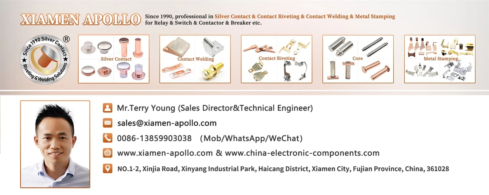
Meeting the strict thermal and electrical breakdown thresholds of 800V fast‑charging architectures requires precise material selection for Metallized Welded Ceramic Housing HVDC contactor internal envelopes. High‑purity alumina ceramics (Al2O3 ≥ 95%) provide the necessary dielectric strength (≥ 20 kV/mm) and thermal shock resistance (ΔT ≥ 300°C) to suppress high‑energy electric arcs under 1000A switching loads, preventing catastrophic short circuits in electric vehicle battery management systems.
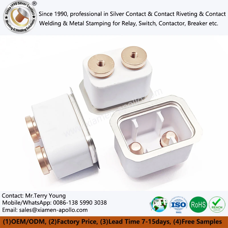
High‑Voltage DC (HVDC) Architecture Demands and Thermal‑Dielectric Challenges
Next‑generation 800V high‑voltage platforms in electric vehicles drive continuous operating currents exceeding 500A and short‑circuit interruption currents up to 3000A. Under these severe operating conditions, standard polymer or low‑grade ceramic housings suffer from surface flashover and thermal cracking due to rapid arc plasma expansion.
To comply with IEC 60947‑4‑1 and ISO 6469‑3 safety standards, EV alumina ceramic housings must maintain structural integrity and insulation resistance exceeding 10¹⁰ Ω at temperatures up to 250°C. The following table compares standard technical specifications between common enclosure materials used in relay manufacturing:
| Material Property | 95%Al2O3 Ceramic | 99%Al2O3 Ceramic | Standard Steatite Ceramic |
|---|---|---|---|
| Dielectric Strength (kV/mm) | ≥ 20 | ≥ 24 | ≥ 12 |
| Flexural Strength (MPa) | ≥ 300 | ≥ 350 | ≥ 140 |
| Thermal Conductivity (W/m·K) | 16‑20 | 25‑30 | 2‑3 |
| Volume Resistivity at 20°C (Ω·cm) | ≥ 10¹⁴ | ≥ 10¹⁵ | ≥ 10¹² |
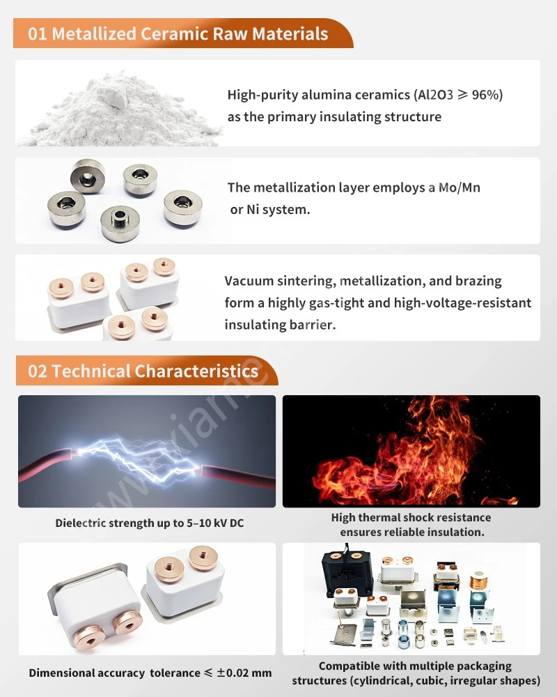
95% Alumina Ceramic Components and High-Temperature Brazing: Interface Control
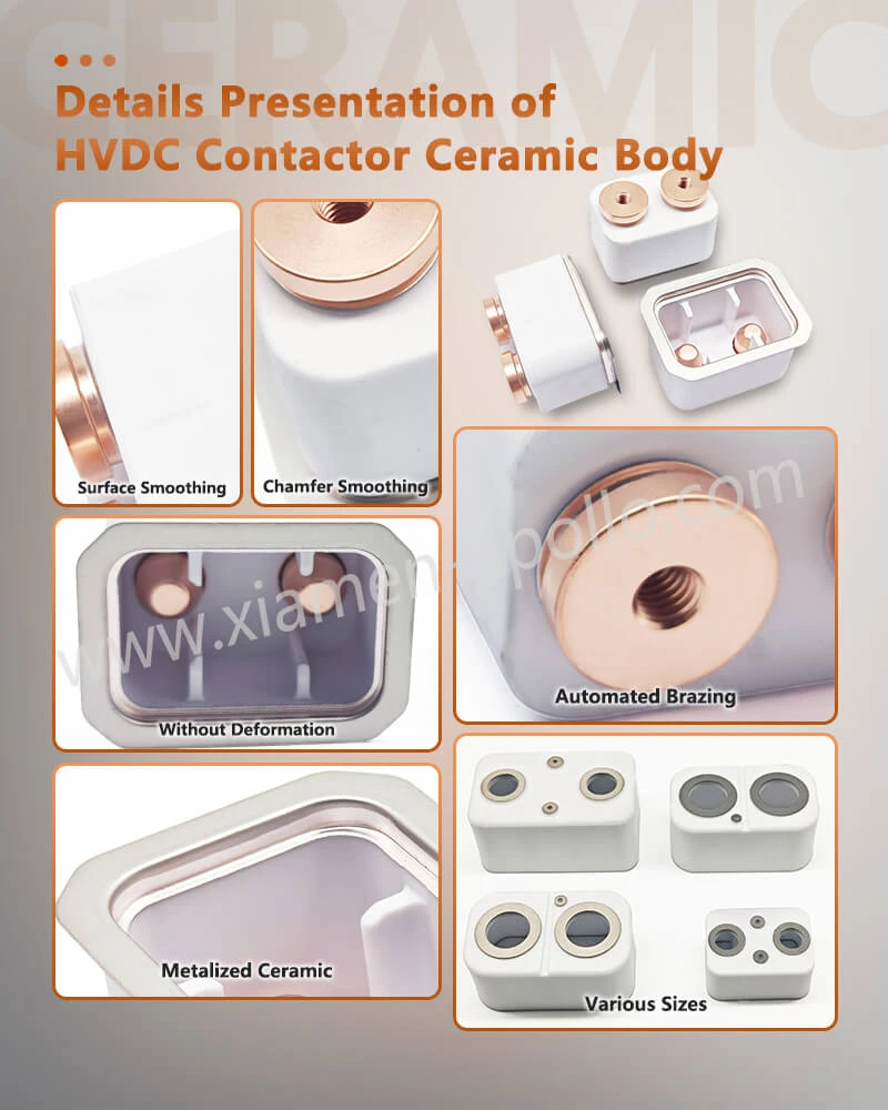
The ceramic enclosure is normally only one part of the assembly. The manufacturing challenge lies at the interface between the ceramic insulating body and the conductive metal structure. A production route using 95% alumina ceramic, T2Y2 copper, and a steel gasket requires controlled forming, surface preparation, metallization or joining preparation, brazing, and dimensional inspection.
EV Alumina Ceramic Housing: material and dimensional controls
An EV Alumina Ceramic Housing used around an HVDC contactor should be specified by material composition, wall thickness, interface geometry, and post-process dimensional stability.
| Component zone | Primary variable | Inspection focus |
|---|---|---|
| Ceramic body | Alumina grade | Material identification |
| Sealing face | Flatness | CMM / optical measurement |
| Metallized zone | Position and coverage | Visual/dimensional inspection |
| Brazing land | Width and geometry | Profile measurement |
| Mounting area | Hole position | CMM |
| Ceramic edge | Chipping and cracking | Microscopic visual inspection |
| Metal interface | Surface condition | Cleanliness/oxidation check |
Ceramic chipping deserves separate control because a small edge defect can affect both mechanical seating and local electrical insulation distance.
Alumina Relay Ceramic Envelope for Electric Automobile: brazed-joint variables
An Alumina Relay Ceramic Envelope for Electric Automobile may combine ceramic insulation with copper and steel components through a controlled brazing operation. The process window should be established around heating rate, peak temperature, holding time, atmosphere, joint clearance, and cooling rate.
The objective is not simply to produce a visually continuous joint. The production process must limit incomplete wetting, excessive filler accumulation, local overheating, and residual stress.
A cross-section inspection can be used during process validation to examine:
| Cross‑section feature | What it indicates |
|---|---|
| Continuous bonded zone | Brazing continuity |
| Local voids | Potential process instability |
| Ceramic cracking | Excessive thermal or mechanical stress |
| Excess filler | Joint geometry or process variation |
| Metallization separation | Interface preparation problem |
| Copper deformation | Thermal or fixture‑related distortion |
For production approval, the inspection method and sampling frequency should be agreed with the customer engineering specification.
Request Free DFM Evaluation & Quote

800V HVDC Current Paths and IEC 60947-4-1: Copper, Contact Resistance and Heat
Current-carrying components inside an HVDC contactor must control resistance at every conductive interface. Heat generation increases with the square of current according to (P=I^2R). Consequently, even a small increase in contact resistance can produce a measurable increase in localized temperature at high current.
This makes the dimensional condition of the conductive interface directly relevant to thermal design.
T2Y2 copper components and contact-resistance control
Copper components can be used as conductive interfaces between the external terminal, contact system, and internal assembly. For a production drawing, the copper grade, thickness, flatness, hole geometry, surface condition, and joining method should be specified.
| Variable | Engineering significance | Recommended control |
|---|---|---|
| Copper grade | Electrical and mechanical behavior | Material certificate |
| Thickness | Current path and mechanical stiffness | Micrometer / CMM |
| Contact area | Current density | Drawing inspection |
| Flatness | Interface pressure | CMM / optical measurement |
| Burr height | Local current concentration and assembly fit | Microscopic inspection |
| Surface oxidation | Joining and electrical interface quality | Surface inspection |
| Joint resistance | Electrical heat generation | Milliohm measurement |
For stamped copper components, progressive die stamping can provide repeatable geometry at production volume, but die wear must be monitored because burr growth and dimensional drift can occur progressively through the tool life.
EV Alumina Ceramic Relay Housing and thermal path design
An EV Alumina Ceramic Relay Housing performs a different function from the copper current path. Its main contribution is electrical insulation, structural separation, and environmental protection.
The engineering interface therefore has two different requirements:
- Electrical path: low and stable resistance through the conductive components.
- Insulation path: controlled clearance, creepage, and dielectric integrity through the ceramic structure.
- The two paths should be evaluated separately before being assessed as a complete contactor assembly.
For high-current applications, thermal simulation should include the resistance of terminals, contact interfaces, busbar connections, and brazed conductive joints. Ceramic temperature should be evaluated together with the surrounding metal structure rather than treated as an isolated material property.
High-frequency brazing and thermal distortion control
High-frequency brazing can concentrate heating around the intended joint region and reduce unnecessary thermal exposure of adjacent components. However, the actual heating profile depends on geometry, material, fixture arrangement, and process parameters.
Process qualification should record:
| Process variable | Control objective |
|---|---|
| Heating rate | Avoid excessive thermal gradients |
| Peak temperature | Achieve required joint formation |
| Holding time | Maintain consistent brazing condition |
| Fixture position | Control assembly alignment |
| Cooling condition | Limit residual thermal stress |
| Joint clearance | Maintain repeatable filler distribution |
The production record should connect these process variables to the component lot and inspection results.
ASTM B117, RoHS and REACH: Surface Oxidation and Environmental Exposure
Metal components used around HVDC ceramic assemblies may experience oxidation during storage, brazing, assembly, and service. Surface condition can affect electrical contact behavior, solderability, or brazing wetting depending on the component.
ASTM B117 can be used as a salt-spray exposure method when the customer qualification plan requires corrosion testing, but it should not be treated as a universal acceptance criterion for every HVDC component. Test duration, specimen configuration, and acceptance limits should be defined by the application specification.
Surface oxidation control for copper and stamped metal parts
For stamped copper, steel, or iron components, surface inspection should distinguish between normal manufacturing discoloration and oxidation that affects the intended joining or electrical interface.
| Surface condition | Potential concern | Control method |
|---|---|---|
| Light discoloration | Cosmetic or process‑related | Visual inspection |
| Heavy oxide film | Brazing/contact interface risk | Surface examination |
| Oil residue | Joining contamination | Cleaning verification |
| Burrs | Assembly and electrical interface | Microscopic inspection |
| Plating damage | Corrosion initiation | Visual / coating inspection |
| Foreign particles | Localized interface resistance | Cleaning control |
The correct surface treatment depends on the metal grade, joining process, and final electrical function. A coating should not be selected only for appearance.
RoHS and REACH material documentation
For procurement teams, RoHS and REACH documentation should be linked to the supplied material and production lot where required by the customer's quality system.
A useful documentation package can include:
Material composition records, supplier certificates, restricted-substance declarations, production lot identification, and applicable inspection reports.
Where corrosion testing is required, ASTM B117 should be listed as the test method, while the customer should define exposure time and acceptance criteria.
Consult Our Electrical Engineers Today
Metallized Alumina Ceramic Relay Case and IEC 60947-4-1: Qualification Data for Supplier Approval
Supplier qualification should separate material verification, dimensional approval, process validation, and functional testing. A first-article sample that meets drawing dimensions does not automatically prove long-term process stability.
EV Alumina Ceramic Housing: first-article inspection data
For an EV Alumina Ceramic Housing, the first-article report should normally identify the drawing revision, material grade, critical dimensions, inspection equipment, and measurement results.
| Approval item | Evidence |
|---|---|
| Ceramic material | Material certificate |
| Critical dimensions | Inspection report |
| Flatness | CMM result |
| Metallization | Visual/dimensional result |
| Brazed joint | Process and section inspection |
| Surface condition | Inspection record |
| Lot identification | Traceability record |
| Packaging | Customer‑approved method where specified |
The inspection report should use the same drawing revision supplied to the production team. Mixing different revisions is a common source of unnecessary approval disputes.
High Voltage DC Ceramic Contactor: electrical and mechanical validation
For a High Voltage DC Ceramic Contactor, validation should reflect the finished assembly rather than only the ceramic material.
Depending on the product specification, the qualification plan can include:
| Test category | Purpose |
|---|---|
| Dielectric withstand | Verify insulation integrity |
| Insulation resistance | Confirm electrical isolation |
| Contact resistance | Verify conductive interface |
| Thermal cycling | Assess dimensional and joint stability |
| Mechanical cycling | Evaluate assembly durability |
| Environmental exposure | Assess specified environmental resistance |
| Visual/cross‑section inspection | Verify joint condition |
IEC 60947 requirements should be applied according to the relevant contactor or switching-device category. The exact test voltage, duration, endurance cycle, and acceptance limits should come from the applicable product specification.
Metallized ceramic joint inspection at production scale
The metallized ceramic interface should receive greater attention when the assembly contains multiple materials with different thermal expansion behavior.
A practical quality-control sequence is:
Drawing review → incoming material verification → ceramic dimensional inspection → metal-part inspection → surface preparation → brazing process control → visual inspection → dimensional inspection → electrical testing → lot release.
This sequence creates a measurable connection between process variables and finished-part quality without relying on appearance-based acceptance.

Frequently Asked Questions
What is the standard helium leak rate threshold for your EV alumina ceramic relay housings?
All mass‑produced EV alumina ceramic relay housings maintain a helium leak rate strictly below 1 × 10⁻⁹ Pa·m³/s, tested using high‑vacuum mass spectrometer leak detectors in compliance with ASTM E2741.
Can Xiamen Apollo customize high‑temperature metallized ceramic relay cases according to proprietary 3D CAD drawings?
Yes. We offer full OEM/ODM custom manufacturing based on customer STEP/IGES files, tailoring metallization patterns, ceramic purity (95% to 99.5%), and brazing alloy compositions to match specific electrical insulation requirements.
What is the typical lead time for custom prototype samples and volume production runs?
Custom prototype samples featuring specialized metallized ceramic envelopes are manufactured, inspected, and shipped within 10 to 15 business days, while volume production runs typically require 10 to 15 business days, depending on order volume.
contact us
Send the latest drawing and target annual volume to start a technical review of EV HVDC Relay Ceramic Housings, brazed assemblies, stamped metal parts, and relay contact components.