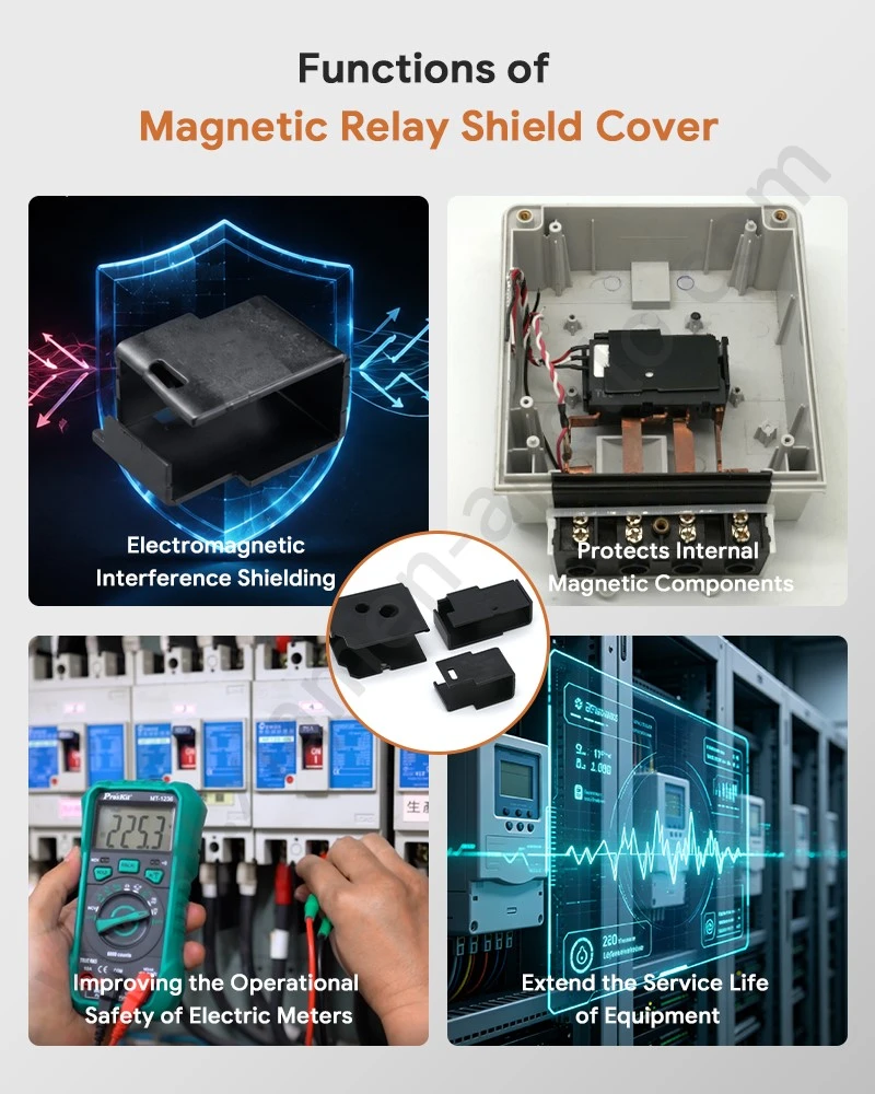
A Relay EMI Shield Cover serves three engineering functions: electromagnetic interference (EMI) control, mechanical protection, and heat transfer. Its effectiveness depends on the steel grade, cover geometry, electrical continuity at mating interfaces, wall thickness, ventilation design, and the frequency and strength of the surrounding electromagnetic fields. For magnetic latching relays, the housing must also accommodate permanent-magnet components and the relay's operating clearances without interfering with its switching mechanism.
A metal cover is therefore a functional component rather than a decorative enclosure. Its material and manufacturing specifications should be matched to the relay's electrical, mechanical, thermal, and electromagnetic requirements.

Electromagnetic Shielding: How a Relay EMI Shield Cover Controls Interference
Shielding Mechanisms at Different Frequencies
A conductive or ferromagnetic metal enclosure can reduce electromagnetic coupling between a relay and nearby electronic circuits. The shielding mechanism depends on the material and frequency range. Reflection and absorption contribute to shielding, while high-permeability materials can redirect magnetic flux under suitable conditions.
Steel is frequently selected for relay covers because it offers a practical combination of mechanical strength, formability, and magnetic properties. However, ordinary low-carbon steel does not provide the same shielding response at every frequency or magnetic-field strength.
| Engineering variable | Effect on shielding | Design consideration |
|---|---|---|
| Material permeability | Influences low-frequency magnetic-flux paths | Verify permeability and magnetic properties for the selected steel grade |
| Electrical conductivity | Affects induced currents and electromagnetic attenuation | Compare the material's conductivity with the target frequency range |
| Wall thickness | Changes absorption and structural stiffness | Establish thickness through shielding and mechanical tests |
| Cover seams and gaps | May allow electromagnetic leakage | Control mating clearances and conductive contact between interfaces |
| Apertures and ventilation slots | Can reduce shielding effectiveness | Evaluate opening dimensions against the relevant frequency range |
| Surface coating | May alter electrical continuity at contact points | Verify coating thickness and contact resistance at mating interfaces |
A closed metal shell does not automatically guarantee effective EMI shielding. Even a small discontinuity at a seam can become significant when the opening dimensions and operating frequency permit electromagnetic leakage. The assembled relay should therefore be tested in its intended configuration.
Magnetic Latching Relay Shield Housing: Special Design Considerations
A Magnetic Latching Relay Shield Housing must accommodate a relay that retains its contact state through a permanent-magnet system or magnetic circuit, depending on its design. The cover's magnetic properties, position, and clearance can affect the surrounding magnetic field and, in some constructions, the relay's operating characteristics.
During design validation, engineers should examine:
- Magnetic-field distribution before and after cover installation.
- Pickup, reset, and latching behavior across the specified operating-voltage range.
- Cover-to-coil and cover-to-armature clearances under dimensional tolerances.
- Shielding effectiveness over the frequencies relevant to the finished equipment.
- Contact resistance at conductive cover joints, where electrical continuity is part of the shielding design.
These checks distinguish a housing that merely fits the assembly from one that meets the relay's electromagnetic requirements.
Shielding Verification and Applicable Standards
Shielding performance should be verified at the finished-product level whenever the enclosure forms part of the electromagnetic design.
| Verification item | Relevant method or reference | Purpose |
|---|---|---|
| Electromagnetic emissions | CISPR 32, where applicable to the finished equipment | Evaluate radiated and conducted emissions |
| Immunity to radiated RF fields | IEC 61000-4-3 | Assess equipment immunity to radiated disturbances |
| Immunity to conducted RF disturbances | IEC 61000-4-6 | Assess susceptibility to conducted RF interference |
| Relay electrical characteristics | IEC 61810-1, where applicable | Verify relevant electromechanical relay requirements |
| Shielding effectiveness | Application-specific test fixture and frequency sweep | Quantify attenuation across the required frequency range |
The applicable standard depends on the relay's end use and the compliance requirements of the complete electrical product. CISPR 32 and IEC 61000-4 test methods should not be interpreted as universal standalone certification requirements for every relay cover.
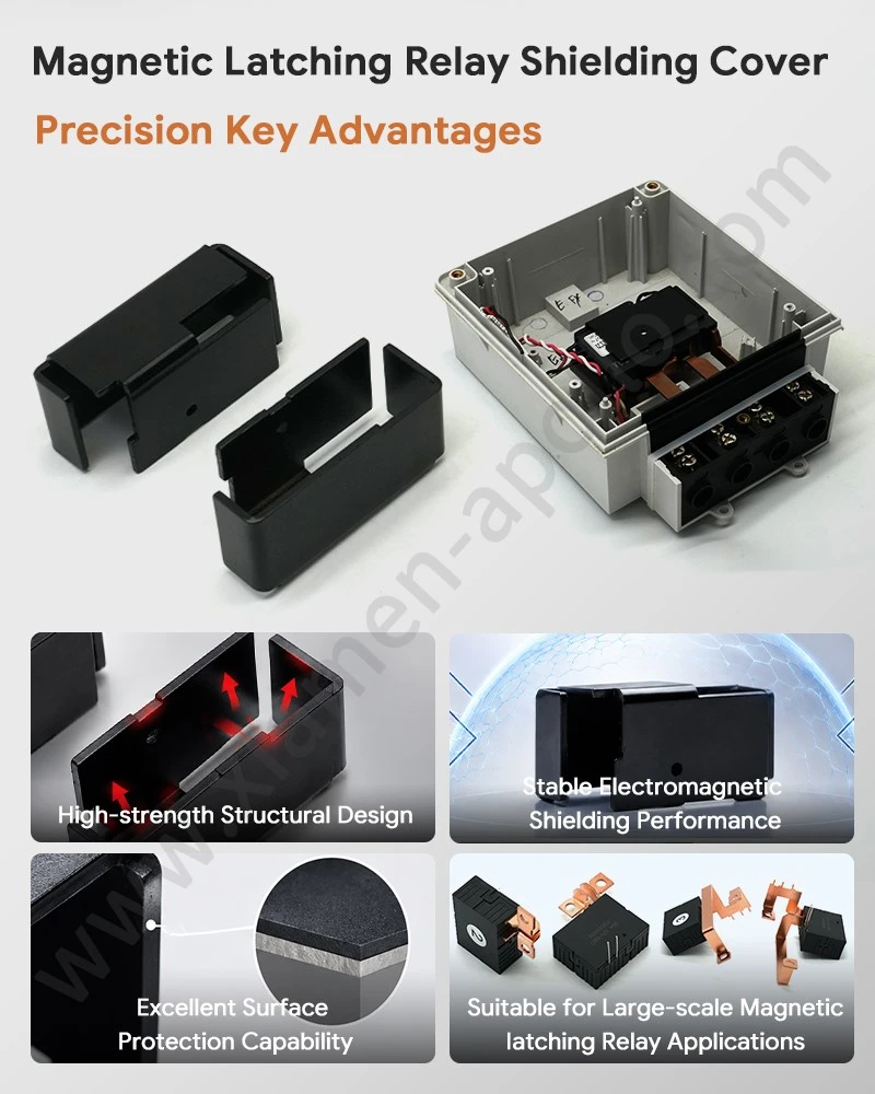
Mechanical Protection: Cover Strength, Forming Accuracy, and Assembly Fit
Impact Resistance and Internal Component Protection
A Magnetic Latching Relay Metal Cover protects the coil, contact mechanism, terminals, and internal supports from accidental contact, handling damage, and transport-related impacts. The degree of protection depends on the cover's material, thickness, shape, fixing method, and clearance from internal components.
The cover should resist permanent deformation under the mechanical loads defined for the relay. Excessive deflection may reduce internal clearances, interfere with armature movement, or cause unintended contact between the cover and electrically active parts.
| Design variable | Potential failure mode | Recommended control |
|---|---|---|
| Sheet thickness | Buckling, denting, or excessive deflection | Validate against defined impact and compression loads |
| Flange geometry | Cracking or local deformation | Inspect bend radii and forming quality |
| Mounting tabs | Loose fit or cover displacement | Verify retention force and assembly dimensions |
| Burr height | Insulation damage or assembly interference | Define deburring and edge-quality acceptance criteria |
| Dimensional tolerance | Coil or armature interference | Control critical dimensions using drawings and inspection plans |
| Surface finish | Corrosion or coating damage | Specify finish according to the service environment |
Progressive Die Stamping for Repeatable Cover Geometry
Progressive die stamping is suitable for high-volume relay covers when the geometry, material, and annual demand justify dedicated tooling. The process can combine blanking, piercing, forming, and cutoff operations in a controlled production sequence.
The main engineering challenge is maintaining the relationship between the cover's mounting features, internal clearance surfaces, and mating edges. Material thickness variation, springback, tool wear, and strip alignment can affect the finished dimensions.
A production control plan should address:
- Incoming steel grade, thickness, and surface condition.
- First-piece dimensional approval after tooling setup.
- Critical flange, hole, and mounting-tab dimensions.
- Burr direction and height at edges near insulation or moving components.
- Periodic tool-condition checks and dimensional capability reviews.
- Corrosion protection and coating integrity after forming.
Specific tolerances must come from the approved engineering drawing and capability study. A value such as ±0.05 mm may be suitable for a particular stamped feature, but it should not be applied universally to every cover dimension without process validation.
Material Selection: Low-Carbon Steel, Stainless Steel, and Other Options
The choice of cover material depends on shielding requirements, corrosion exposure, forming complexity, cost, and magnetic interaction with the relay.
| Material option | Main engineering characteristics | Typical selection considerations |
|---|---|---|
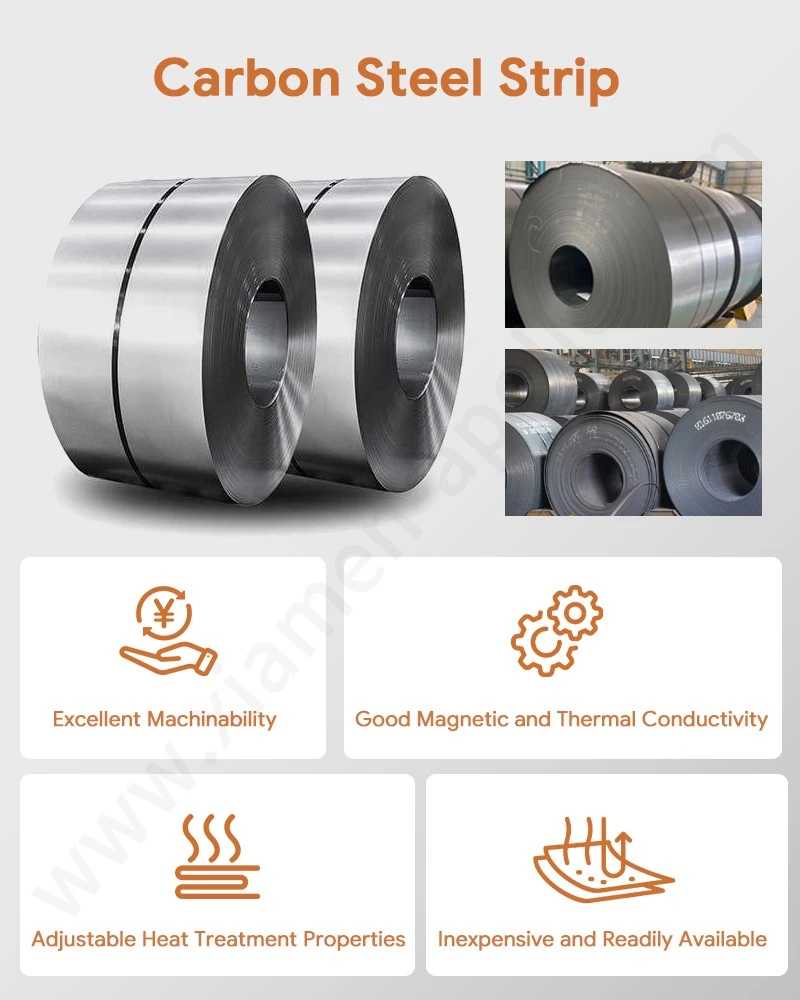
| Low-carbon steel | Good formability, practical strength, and ferromagnetic behavior | General-purpose stamped relay covers where corrosion protection is specified |
| Stainless steel | Corrosion resistance varies by grade; magnetic response also varies | Environments requiring improved corrosion resistance, subject to magnetic and forming evaluation |
| Nickel-plated steel | Steel substrate with a plated surface | Applications requiring a specified surface finish or corrosion-control system |
| Copper or copper alloy | High electrical conductivity; generally lower magnetic permeability than ferromagnetic steel | Specialized shielding designs where conductivity and field frequency justify the material |
Material selection should be based on the actual shielding mechanism rather than the assumption that every metal provides equivalent performance. Coatings and plating must also be evaluated for adhesion, corrosion resistance, and electrical continuity at assembly interfaces.
Dimensional Inspection and Quality Documentation
For repeat production, dimensional verification should focus on features that affect fit, retention, shielding continuity, and internal clearance.
| Quality checkpoint | Inspection approach | Record or acceptance basis |
|---|---|---|
| Sheet thickness | Calibrated thickness gauge or micrometer | Approved drawing and material specification |
| Hole and flange positions | Optical measurement system or CMM, as appropriate | Drawing tolerances |
| Burrs and edge condition | Visual inspection and dimensional measurement | Approved workmanship criteria |
| Coating thickness | Suitable coating-thickness measurement method | Plating or coating specification |
| Corrosion resistance | ASTM B117 salt-spray exposure, where specified | Customer-approved test duration and acceptance criteria |
| Quality management | ISO 9001 or IATF 16949, where applicable | Supplier certification scope and customer requirements |
ASTM B117 defines a salt-spray test practice; it does not independently establish a universal pass/fail duration for relay covers. Similarly, IATF 16949 applies to automotive quality-management systems within its defined scope, not automatically to every industrial relay component.
Download Contact Material Spec Sheet
Thermal Management: Heat Transfer and Operating Temperature
How a Metal Relay Cover Transfers Heat
A metal cover can transfer heat from internal components to the surrounding air or to adjacent mounting structures. The actual thermal benefit depends on the heat source, contact between components, cover material, exposed surface area, airflow, and the temperature difference between the relay and its environment.
Heat can reach the cover through conduction from internal supports and through convection or radiation within the enclosure. The cover then dissipates heat through its external surfaces. However, a thin steel cover is not automatically an effective heat sink, and its thermal contribution must be assessed against the relay's total heat generation.
Relevant heat sources include:
- Coil winding losses during continuous energization.
- Contact resistance at closed contacts under load.
- Resistive losses at terminals and internal conductive joints.
- Localized heating caused by degraded or unstable electrical connections.
Thermal Conductivity Comparison of Common Cover Materials
Material thermal conductivity affects heat spreading through the cover, but it does not determine the temperature of the complete relay by itself.
| Material | Approximate thermal conductivity at room temperature | Thermal design implication |
|---|---|---|
| Low-carbon steel | 45–60 W/(m·K) | Moderate heat spreading with useful structural strength |
| Austenitic stainless steel | 14–20 W/(m·K), grade-dependent | Lower heat spreading than common carbon steel grades |
| Copper | 380–400 W/(m·K) | High heat spreading, subject to cost, strength, and design constraints |
| Aluminum | 200–235 W/(m·K), alloy-dependent | High heat spreading with lower density than steel |
These figures are indicative material ranges, not guaranteed values for every grade, temper, coating, or operating temperature. Actual design calculations should use the selected material's verified data.
Temperature Rise, Contact Resistance, and Thermal Validation
Contact resistance is a key variable in relay heating. A rise in contact resistance can increase localized resistive heating under load, while coil losses contribute to the internal temperature rise during energization.
Thermal validation should measure the relay under defined electrical and environmental conditions, including:
- Rated coil voltage and the specified duty cycle.
- Contact current and load characteristics.
- Ambient temperature and airflow.
- Temperature at the coil, contact terminals, and other defined measurement points.
- Steady-state temperature rise after the specified stabilization period.
IEC 61810-1 should be consulted for applicable electromechanical relay requirements, while the finished product's own specification determines the test conditions and acceptance limits. Temperature-rise limits should not be assigned solely from the cover material or its thermal conductivity.
Integrating EMI Shielding, Mechanical Strength, and Thermal Performance
Design Trade-Offs for Magnetic Latching Relay Metal Covers
The three main functions of a relay cover can impose competing design requirements. Increasing sheet thickness may improve stiffness and electromagnetic absorption in some conditions, but it can increase mass, forming loads, and package dimensions. Adding openings may improve airflow while reducing shielding effectiveness. Selecting a highly conductive material may improve heat spreading without providing the magnetic properties required by a particular low-frequency shielding design.
| Design objective | Key parameters | Validation method |
|---|---|---|
| EMI shielding | Material properties, thickness, seam continuity, aperture geometry | Shielding or system-level EMC testing |
| Mechanical protection | Thickness, flange design, retention force, forming quality | Impact, compression, retention, and dimensional tests |
| Thermal performance | Thermal conductivity, surface area, airflow, component losses | Temperature-rise testing under defined loads |
| Magnetic compatibility | Permeability, cover position, coil and armature clearance | Latching, pickup, reset, and magnetic-field checks |
| Corrosion protection | Base material, coating, edge coverage, environment | Coating inspection and specified corrosion testing |
| Production consistency | Tool condition, material variation, critical dimensions | Process control, inspection records, and capability analysis |
The preferred design is the one that meets the finished relay's defined requirements, not necessarily the cover with the greatest thickness or highest thermal conductivity.
Manufacturing Controls for Custom Relay Shield Covers
A manufacturing specification for a Relay EMI Shield Cover should identify the following information before tooling approval:
Material grade and thickness, including permitted variation.
- Flat-pattern geometry, bend radii, and critical formed dimensions.
- Hole positions, mounting features, and assembly datums.
- Burr direction, edge condition, and surface-finish requirements.
- Plating or coating type, thickness, and corrosion-test criteria.
- Required sample inspection, measurement reports, and traceability records.
- Annual demand, batch quantity, packaging method, and delivery requirements.
For automotive applications, supplier quality controls should be aligned with the customer's requirements and the applicable quality-management framework. RoHS and REACH documentation should reflect the actual material and coating composition; neither should be claimed solely based on a supplier's general statement.
A drawing review before production helps identify conflicting requirements, such as a narrow forming radius combined with a thick sheet, a conductive coating interrupted at a critical joint, or an opening that compromises the required shielding frequency range.
Consult Our Electrical Engineers Today
Frequently Asked Questions
1. How can the EMI shielding effectiveness of a relay metal cover be verified?
Test the assembled relay or defined enclosure using an appropriate shielding or EMC test method across the required frequency range. The test setup, grounding, cable arrangement, seam configuration, and acceptance limits should be documented before testing.
2. What information is required to obtain a quotation for a custom Magnetic Latching Relay Metal Cover?
Provide a 2D drawing or 3D model, material grade, sheet thickness, critical tolerances, surface treatment, annual demand, batch quantity, and required inspection documents. Tooling cost, prototype lead time, and mass-production lead time should be quoted separately.
3. Can a supplier provide IATF 16949 and RoHS/REACH documentation for a Relay EMI Shield Cover?
Where applicable, request a valid quality-management certificate within the supplier's certified scope, along with material declarations and coating-composition documentation. RoHS and REACH status should be verified against the actual component materials and applicable regulatory requirements.
contact us
Share your drawings and volume forecast now to get our factory's full DFM review for a custom Relay EMI Shield Cover, with in-house progressive stamping and IATF16949 traceability ready for urgent OEM validation.