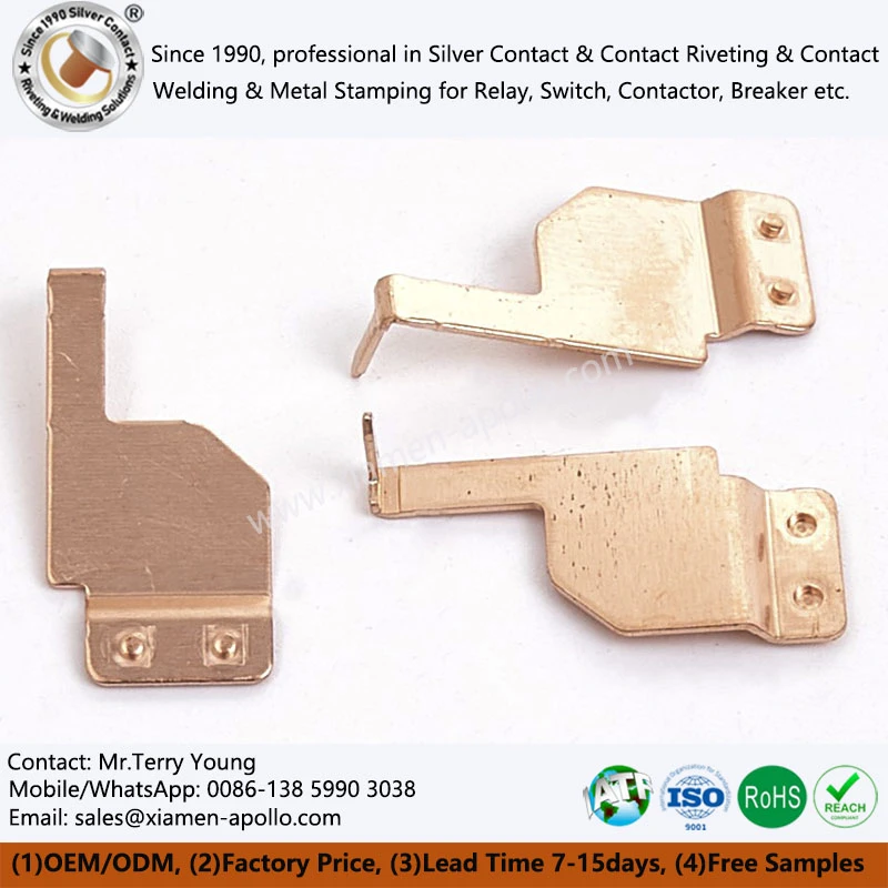
Smart home appliance copper stamping terminals must maintain stable electrical connections within restricted installation spaces while carrying continuous current through repeated operating cycles. Terminal selection therefore depends on copper alloy conductivity, cross-sectional area, contact pressure, dimensional tolerance, and resistance to mechanical relaxation. C1100 copper is suitable for designs prioritizing electrical conductivity, while C2680 brass provides a practical balance of conductivity, strength and stamping formability.
Smart switches, intelligent sockets, thermostatic controllers, motor control modules and household appliance switching assemblies increasingly integrate multiple electrical functions into compact enclosures. This reduces the available space for terminal installation and increases the importance of dimensional consistency and thermal management.
A stamped copper terminal is not simply a conductive metal strip. Its geometry determines current distribution, heat generation, insertion force, retention force and mechanical stability throughout the product's service life.
C2680 Brass vs. C1100 Copper: Material Selection and ASTM B152 Requirements
Selecting between C2680 brass and C1100 copper requires evaluating electrical conductivity, tensile strength, forming behavior and connection requirements together.
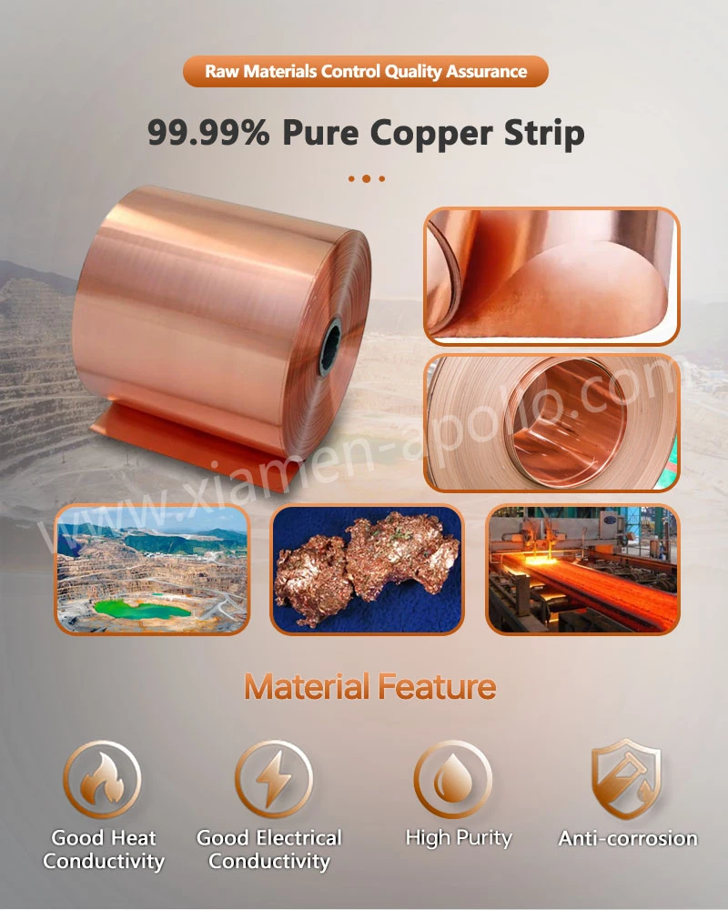
C1100 is commercially pure copper with high electrical conductivity. C2680 is a copper-zinc alloy commonly used for stamped electrical components where forming performance and mechanical strength are important.
Neither material is universally suitable for every appliance terminal. The correct choice depends on current loading, terminal geometry, joining method and mechanical retention requirements.
C1100 Copper: High Conductivity for Current-Carrying Terminals
C1100 copper is commonly selected for electrical components requiring low bulk resistance.
Its main engineering characteristics include:
- High electrical conductivity, commonly around 100% IACS for qualifying material conditions.
- High thermal conductivity for heat transfer.
- Good electrical joining and soldering characteristics with appropriate surface preparation.
- Suitable ductility for bending and stamping in appropriate temper conditions.
- Compatibility with tin, silver and nickel surface finishes.
For smart appliance terminals, C1100 is particularly relevant when conductor cross-section and electrical losses are major design constraints.
However, pure copper is relatively soft compared with many copper alloys. Repeated insertion and removal can produce local deformation, especially at spring-contact sections.
The material temper and formed geometry must therefore be evaluated together.
C2680 Brass: Mechanical Strength and Stamping Formability
C2680 brass contains approximately 65% copper and 35% zinc by nominal alloy composition.
Its characteristics include:
- Higher mechanical strength than commercially pure copper in comparable conditions.
- Good cold-forming and stamping characteristics.
- Suitable performance for punched holes, formed tabs and terminal bodies.
- Lower electrical conductivity than C1100.
- Good compatibility with commonly used protective plating systems.
C2680 is frequently considered for appliance electrical terminals where mechanical retention, dimensional stability and production efficiency are important.
For spring-contact structures, the selected temper is particularly important because forming operations and repeated mechanical loading can affect permanent deformation.
C2680 vs. C1100: Electrical and Mechanical Property Comparison
| Engineering parameter | C1100 copper | C2680 brass |
|---|---|---|
| Nominal composition | ≥99.90% Cu | Approx. 65% Cu, 35% Zn |
| Electrical conductivity | Approx. 100% IACS for qualifying conditions | Commonly around 25–30% IACS, depending on condition |
| Mechanical strength | Depends strongly on temper | Generally higher in comparable conditions |
| Thermal conductivity | High | Lower than C1100 |
| Stamping formability | Good with suitable temper | Good for many terminal geometries |
| Spring-contact suitability | Requires appropriate temper and design | Requires appropriate temper and forming validation |
| Typical selection priority | Low electrical resistance | Mechanical strength and formability |
Contact Force, Insertion Cycles and Dimensional Stability: IEC 60512 Testing
Electrical terminals must maintain sufficient contact force to prevent unstable connections during normal operation and mechanical cycling.
In smart home appliances, terminals may experience repeated plug insertion, spring deformation, vibration and temperature fluctuations. These conditions can change the contact interface and increase electrical resistance.
The mechanical design must therefore balance initial contact force, elastic deformation, stress distribution and long-term force retention.
Contact Pressure and Electrical Resistance: Four-Wire Kelvin Measurement
Contact resistance depends on the actual conductive contact area, surface condition, contact pressure and material properties.
Even when two terminals have identical nominal dimensions, differences in surface roughness, plating thickness and contact geometry can produce different resistance values.
Important design variables include:
- Contact-point radius and effective contact width.
- Surface roughness and stamping-related deformation.
- Contact pressure at the mating interface.
- Tin or nickel plating thickness.
- Oxide and contamination conditions.
- Local temperature during continuous current operation.
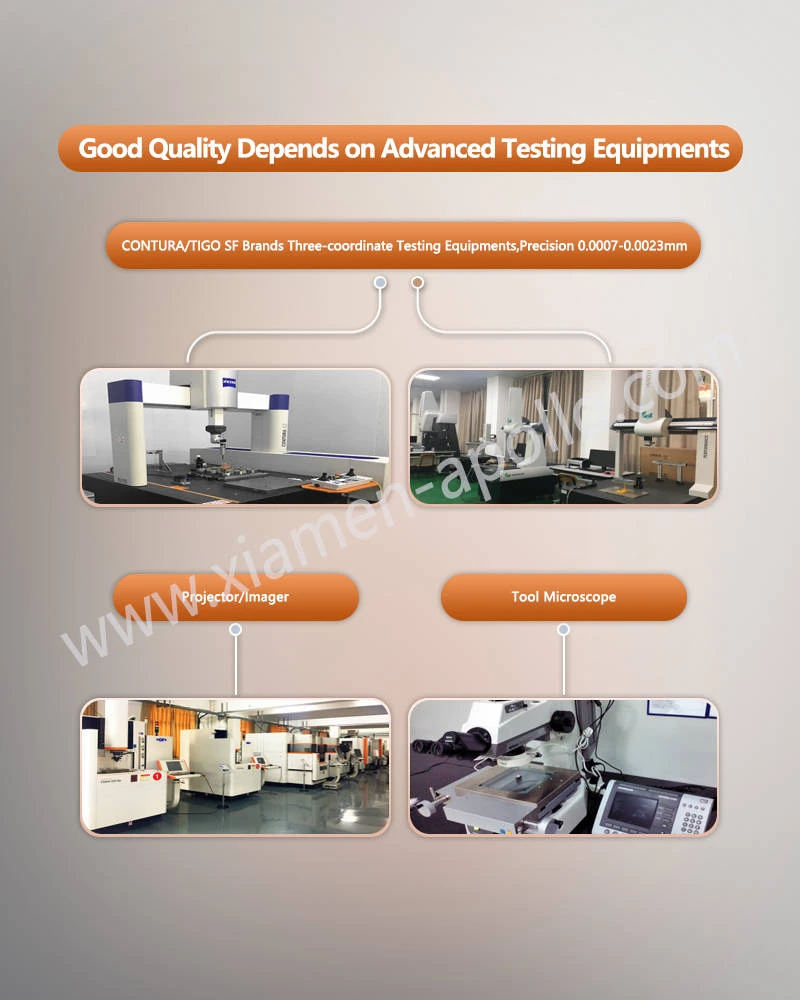
Four-wire Kelvin measurement is recommended for low-resistance terminal evaluation because it reduces the influence of lead and connection resistance.
Resistance measurements should be conducted under defined contact force, current and environmental conditions.
Insertion and Withdrawal Force: IEC 60512 Mechanical Verification
Insertion force and withdrawal force are important indicators of terminal mating performance.
If insertion force is too high, assembly equipment may deform the terminal or damage the housing. If retention force is too low, vibration or repeated handling may cause intermittent electrical connections.
The following variables require control:
| Control parameter | Engineering concern | Verification method |
|---|---|---|
| Insertion force | Excessive assembly load | Force-displacement measurement |
| Withdrawal force | Insufficient mechanical retention | Pull-out force testing |
| Contact resistance | Electrical instability | Four-wire Kelvin measurement |
| Permanent deformation | Loss of spring force | Dimensional and force comparison |
| Plating condition | Wear and corrosion | Microscopy and coating-thickness measurement |
IEC 60512 provides test methods for electrical connectors. The applicable test method should be selected according to the terminal's connection structure and intended use.
Repeated Mating Cycles: 500–10,000 Cycle Design Validation
The required mating-cycle life depends on the appliance's expected maintenance, installation and operating conditions.
A design validation program may use 500, 1,000, 5,000 or 10,000 mating cycles as project-specific test levels.
These values are proposed test levels, not universal IEC requirements.
During cycling, engineers should monitor:
- Insertion and withdrawal force changes.
- Contact resistance before and after cycling.
- Permanent deformation of spring sections.
- Plating wear at the contact interface.
- Cracks or localized material damage.
- Changes in terminal positioning.
For spring terminals, the initial force value alone cannot establish service-life suitability. Force retention after cycling provides additional information about material temper and geometric stability.
Springback and Forming Accuracy: ±1° Bending Control
Springback occurs when elastic recovery changes the final geometry after a stamping or bending operation.
The magnitude depends on:
- Material yield strength.
- Material thickness.
- Bend radius.
- Grain direction.
- Die geometry.
- Forming sequence and clearance.
C2680 brass and C1100 copper may exhibit different springback behavior under the same tooling conditions.
Tooling compensation should therefore be established through trial stamping and dimensional feedback.
For critical spring-contact structures, inspection should include both unloaded geometry and functional force testing.
Engineering FAQ: Copper Stamped Parts Components OEM Procurement
Q1. How do manufacturers verify the tin plating thickness of Copper Stamped Parts Components?
Tin plating thickness is commonly measured using X-ray fluorescence (XRF) coating-thickness equipment. Cross-sectional metallographic analysis can provide additional verification when coating structure or interface quality requires examination. Measurement locations and acceptance limits should be defined in the inspection specification.
Q2. What is the typical sample lead time for custom brass and Copper Spring Electrical Parts?
Sample lead time depends on whether existing tooling can be used. Samples from existing dies can be arranged after drawing and material confirmation. New progressive die development requires additional tooling design, fabrication, trial stamping and dimensional approval. A confirmed delivery schedule should be provided after reviewing the drawings.
Q3. What documents should buyers request when purchasing C2680 or C1100 stamped electrical terminals?
Buyers should request material certificates identifying alloy grade and temper, dimensional inspection reports, plating specifications, applicable RoHS and REACH declarations, and batch traceability records. For automotive-related programs, relevant IATF 16949 quality-system evidence should also be reviewed.
contact us
Submit your electrical metal stamping part drawings and annual demand forecast now. Request a technical review of material selection, stamping feasibility, critical tolerances, and production tooling before your next appliance development milestone.