

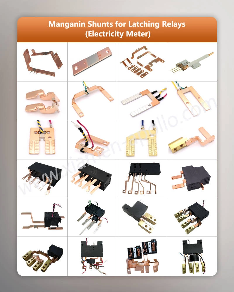
An EBW Manganin Shunt for Electronic Meter converts high current into a measurable millivolt signal through a defined low-resistance path. The basic structure combines a manganin resistance section with copper current terminals, with the two dissimilar metals joined by electron beam welding before precision stamping. The resulting shunt can be designed around specified current, resistance, temperature coefficient, voltage-drop, and dimensional requirements.
For electronic metering, the component is not simply a piece of low-value resistance metal. The welding transition, manganin geometry, copper terminal resistance, sensing-point location, and thermal behavior all affect the voltage signal delivered to the meter's measurement circuit.

Copper-Manganin EBW For Manganese Copper Resistance Shunt: Why the Joint Matters
The Resistance Element and Current Terminal Have Different Roles
Manganin Shunt for Energy Meters adopts dissimilar materials to satisfy different electrical‑function requirements. Manganin acts as the resistive element with a controlled resistance value, while copper provides low‑resistance current paths and external connection terminals. The critical engineering challenge lies in the transition zone between these two materials.
| Properties | Manganin | Copper |
|---|---|---|
| Core Function | Resistive element | Current‑carrying terminal |
| Relative Resistivity | High | Low |
| Primary Design Purpose | Generate defined voltage drop | Transfer current with minimum loss |
| Thermal Property | Low TCR characteristic | High electrical and thermal conductivity |
| Forming Role | Resistive zone | Terminals and current‑carrying paths |
| Joint Requirement | Controlled transition | Controlled transition |
Full‑copper construction delivers excessively low resistance and prevents compact sensing‑element design. Full‑manganin construction raises terminal resistance and heat generation. For this reason, copper‑manganin hybrid structures are implemented for practical shunt products.
EBW Bonding of Composite Strip before Stamping
Manufacturing workflow: Copper strip + Manganin strip → Edge alignment → Electron‑beam welding → Welded composite strip → Stamping → Inspection
Electron‑beam welding is completed before stamping operations. This process produces continuous composite strips of copper and manganin, which are then processed into finished parts via progressive stamping.
Differences Between EBW, Brazing and Solder Joints
Solder‑based and brazed shunts introduce extra filler materials at copper‑to‑manganin interfaces. EBW creates metallurgical bonding by melting base materials directly.
| Joint Structure | Bonding Medium | Key Process Variables | Core Engineering Considerations |
|---|---|---|---|
| Soldered | Solder alloy | Solder thickness, wetting condition | Extra electrical and thermal interfaces |
| Brazed | Brazing filler metal | Filler distribution, welding temperature | Filler layer disturbs current paths |
| EBW | Base‑material fusion | Beam current, focusing, alignment | Controlled fusion of dissimilar metals |
| Resistance Weld | Electrode‑induced local fusion | Current, pressure, hold time | Heat‑affected zone dimension |
For Electricity Meter Shunts used in electronic meters, welded zones count as functional electrical areas instead of simple mechanical connection points.
EBW Process Control
Key electron‑beam welding variables include:
- Thickness of copper and manganin strips
- Surface condition of raw materials
- Strip edge‑alignment accuracy
- Electron‑beam current
- Acceleration voltage
- Focal‑point position
- Welding travel speed
- Vacuum level
- Weld penetration depth
- Geometry of fusion zones
Parameter validation shall be performed for specific material combinations and strip dimensions. Generic EBW parameters cannot be applied without verification.
Consult Our Electrical Engineers Today

Internal Integration vs. External Separation of Energy Meter Shunts: Structural Trade‑Offs
Meter designers must balance spatial configuration and thermal dissipation when deciding between internal integrated shunts and external split setups.
Structural Performance Comparison
| Evaluation Metric | Internal Integrated Shunt | External Split Shunt Assembly |
|---|---|---|
| Signal Voltage Level | Low Voltage (6mV) | High Voltage (75mV) |
| Power Dissipation (300A) | 1.8 VA | 22.5 VA |
| Accuracy Class Capability | Class 0.5 / Class 0.2 | Class 1.0 / Class 1.5 |
| Tamper Resistance | High (Internal sealed encapsulation) | Moderate (Requires secure cabling) |
Frequently Asked Questions about Manganin Shunt with for Energy Meter
What is the typical resistance tolerance achievable for mass‑produced EBW Manganese Copper Shunts?
Our production lines consistently maintain resistance tolerances within ± 1% to ± 3%, with high‑precision custom grades sorted down to ± 0.5% depending on client specifications and application requirements.
How does electron beam welding prevent resistance drift over time?
Electron beam welding eliminates intermediate filler solders, creating a homogeneous atomic bond between the manganin alloy and copper terminals that resists thermo‑mechanical fatigue and oxidation under continuous loads.
What is the standard sample lead time and production capacity for OEM orders?
Standard custom prototype samples are delivered within 10 to 15 business days, while full‑scale mass production orders operate on a standard 10 to 15 business days delivery window backed by IATF16949 quality controls.
contact us
Leverage direct factory manufacturing capabilities, advanced electron beam welding lines, and rigorous IEC compliance testing for your EBW Manganin Shunt for Electronic Meter applied in next‑generation smart meters and EV infrastructure. Contact our engineering team today to upload your CAD drawings and receive a comprehensive DFM and cost‑optimized quotation within 24 hours.
