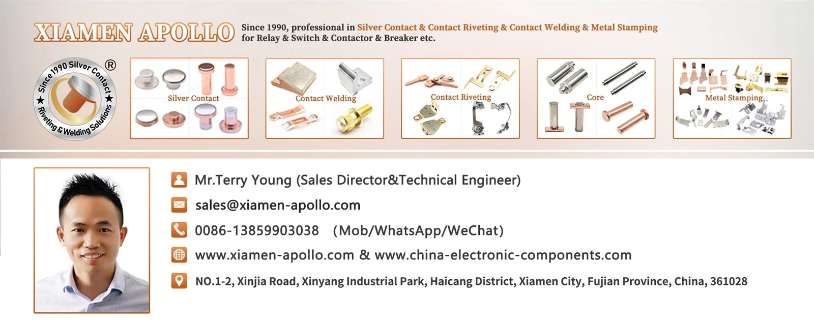
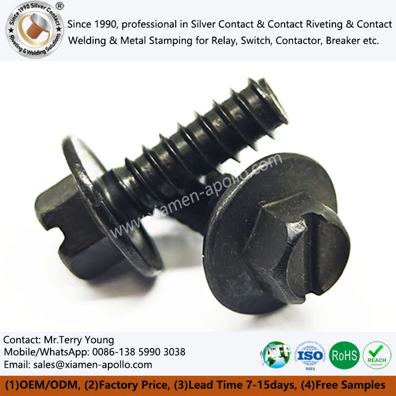
A Flanged Hexagon Head Bolt Screw combines a hexagonal drive head with an integrated flange that distributes bearing pressure across the joint surface. In engine assemblies, joint stability depends on the fastener's material grade, thread geometry, flange contact area, installation torque, and resistance to thermal cycling and vibration. Correct specification and controlled tightening help maintain clamping force, reduce joint movement, and limit the risk of leakage or component damage.
How Flanged Hexagon Head Bolt Screws Support Engine Joint Stability
Load Distribution Through the Integral Flange
A Flanged Screw with Hexagonal Head incorporates a load-bearing flange beneath the hexagonal head. Compared with a conventional hex-head bolt of similar thread size, the flange provides a larger bearing surface, reducing local contact pressure when the mating surfaces are flat, clean, and dimensionally suitable.
The flange does not automatically prevent loosening. Its effectiveness depends on flange diameter, bearing-face flatness, surface finish, joint stiffness, and the applied preload. Serrated flange designs may provide additional resistance to rotation in approved applications, but they can damage coatings or mating surfaces and should not be substituted without engineering approval.
Engine Components and Joint Requirements
A Hexagon Flange Headed Bolt Fastener may be used in engine brackets, accessory mounts, covers, housings, and other threaded joints, subject to the assembly drawing and service conditions.
| Joint application | Primary engineering concern | Specification consideration |
|---|---|---|
| Engine accessory brackets | Vibration and transverse loading | Preload retention, thread engagement, fatigue resistance |
| Engine covers and housings | Fluid leakage and surface distortion | Flange geometry, gasket compression, tightening sequence |
| Structural mounting points | Cyclic tensile and shear loading | Fastener strength class, joint stiffness, fatigue assessment |
| High-temperature engine interfaces | Thermal expansion and preload variation | Material strength at service temperature, thermal cycling |
| Corrosion-exposed assemblies | Rust and thread damage | Coating compatibility, corrosion testing, service environment |
Fastener selection must reflect the actual joint rather than the engine category alone. A bolt used on a low-temperature accessory bracket may require different material and coating specifications from one exposed to hot oil, coolant, exhaust-adjacent temperatures, or repeated thermal cycling.
Failure Mechanisms in Engine Fastened Joints
A loose or damaged bolt can permit relative movement between connected components. Depending on the joint, this movement may lead to fretting, gasket relaxation, fluid leakage, hole elongation, or fatigue cracking.
Common failure mechanisms include:
- Preload loss: Embedment, gasket compression, thermal cycling, or joint movement reduces the original clamping force.
- Thread stripping: Insufficient thread engagement, excessive installation torque, or weak internal threads cause thread failure.
- Fatigue fracture: Repeated cyclic loading initiates and propagates cracks, especially where stress concentrations are present.
- Corrosion-related damage: Surface corrosion reduces the remaining section and can increase removal torque or cause thread seizure.
- Bearing-surface deformation: Excessive local pressure damages the flange or mating surface, changing the joint's load distribution.
A failure investigation should record the fracture location, thread condition, flange impressions, corrosion pattern, and assembly history. Replacing the fastener without identifying the initiating mechanism may allow the same failure to recur.
Download Contact Material Spec Sheet
Material Selection for High-Temperature and High-Vibration Engine Fasteners
Alloy Steel Grades and Mechanical Strength
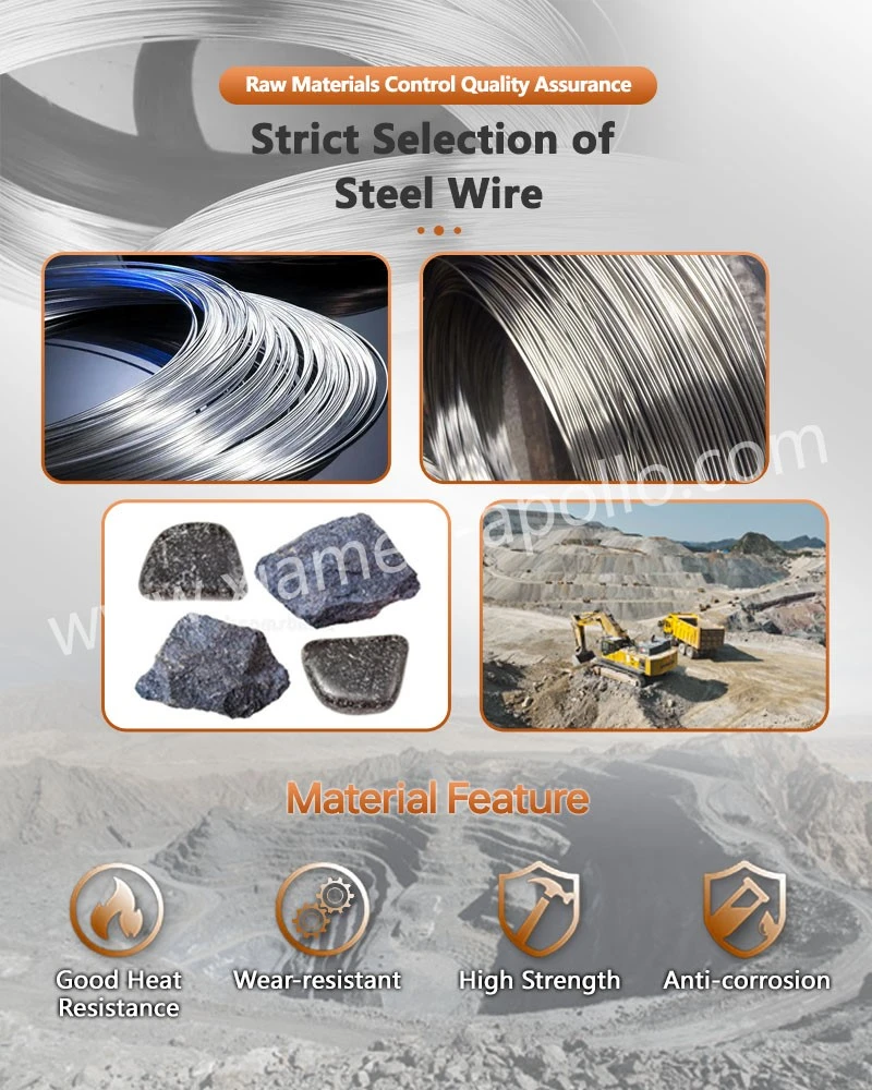
High-strength alloy steel is widely used for threaded fasteners that require substantial tensile capacity and fatigue resistance. However, the designation "alloy steel" alone does not establish suitability for an engine application. The specified grade, heat treatment, hardness range, coating system, and service temperature must be evaluated together.
For metric steel fasteners, ISO 898-1 defines mechanical and physical properties for specified property classes. Common classes include 8.8, 10.9, and 12.9, but the highest class is not automatically the best choice for every joint. Higher strength may increase sensitivity to hydrogen embrittlement under certain coating and processing conditions.
| Property or specification | Engineering relevance | Verification method or reference |
|---|---|---|
| Property class 8.8, 10.9, or 12.9 | Establishes specified mechanical properties for covered carbon and alloy steel fasteners | ISO 898-1 |
| Tensile strength and proof load | Determines resistance to axial loading and permanent deformation | Applicable ISO 898-1 requirements |
| Hardness | Helps verify material condition and heat-treatment consistency | Applicable product specification and test method |
| Thread geometry and tolerance | Affects assembly fit, load distribution, and torque-to-preload behavior | ISO metric thread specifications, such as ISO 965 |
| Coating thickness and friction | Influences corrosion resistance and the preload achieved at a given torque | Drawing requirements and coating-specific standards |
| Elevated-temperature strength | Determines whether mechanical properties remain adequate in service | Application-specific material data and validation testing |
Values must be taken from the applicable standard edition and product specification. A property class does not, by itself, guarantee a particular fatigue life, corrosion rating, or suitability for continuous exposure to elevated temperatures.
Thermal Cycling, Fatigue, and Material Selection
Engine fasteners experience temperature changes that can alter the relative expansion of the bolt and clamped components. The resulting preload change depends on material expansion coefficients, grip length, joint stiffness, temperature distribution, gasket behavior, and the initial tightening condition.
Fatigue resistance is also affected by thread-root geometry, surface condition, residual stresses, and cyclic load amplitude. In many threaded joints, the first engaged thread carries a significant portion of the thread load, making thread quality and geometry important to durability.
For hot engine interfaces, engineers should confirm:
- The maximum and cyclic service temperatures.
- The fastener's specified mechanical properties at the relevant temperature.
- The thermal expansion characteristics of the bolt and mating components.
- The effects of the coating or lubricant on friction and tightening consistency.
- Whether the joint requires a specific tightening sequence, retightening procedure, or replacement rule.
Do not assume that a standard room-temperature tensile-strength value remains valid at elevated temperature. Use applicable material data and validate the joint under representative operating conditions.
2.3 Corrosion Protection and Coating Compatibility
Corrosion protection must be selected according to the service environment and the joint's electrical, thermal, mechanical, and chemical requirements. Zinc-based coatings, zinc flake systems, and other engineered finishes may be considered where permitted by the design.
| Protection approach | Potential benefit | Engineering limitation |
|---|---|---|
| Zinc-based coating | Provides sacrificial corrosion protection in suitable environments | Coating thickness, friction, temperature limits, and hydrogen-embrittlement controls require review |
| Zinc flake coating | Can provide corrosion resistance with controlled coating systems | Performance depends on the coating system, application, and specified test method |
| Phosphate-based finish with approved lubricant | Can help control friction during assembly | Usually requires a separate corrosion-protection strategy for demanding environments |
| Stainless steel fastener | Provides corrosion resistance in selected environments | Strength, galling risk, thermal behavior, and galvanic compatibility require evaluation |
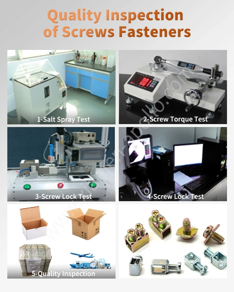
ASTM B117 describes a salt-spray testing practice. Results from this test should not be treated as a direct prediction of service life because laboratory exposure does not reproduce every field condition. The acceptance criterion, exposure duration, substrate, coating system, and corrosion failure definition should be stated in the purchase specification.
For coated high-strength steel fasteners, the manufacturing process must also address hydrogen-embrittlement risk where applicable. Coating selection and post-treatment requirements should follow the relevant fastener standard, coating specification, and approved process controls.
Tightening Torque and Preload Control for Engine Assembly
Why Installation Torque Must Be Controlled
A Fastening Screw with Flange and Hex Head is typically tightened by applying torque to generate axial preload in the fastener. This preload clamps the connected parts together and helps prevent joint separation under service loads.
Torque is not a direct measurement of bolt tension. A substantial portion of the applied torque is consumed by friction at the threads and beneath the bolt head or flange. Changes in lubrication, coating, surface finish, thread condition, or reuse can therefore produce different preload values at the same nominal torque.
Excessive torque may cause yielding, thread stripping, flange indentation, or distortion of the connected component. Insufficient torque may allow joint slip, gasket leakage, and fatigue loading caused by repeated movement.
Torque, Friction, and Preload: Engineering Comparison
| Assembly variable | Effect on the joint | Required control |
|---|---|---|
| Applied tightening torque | Generates preload through thread and bearing friction | Use the approved assembly specification |
| Thread friction | Changes the relationship between torque and axial force | Specify coating, lubricant, and thread condition |
| Under-flange friction | Influences the torque needed to rotate the fastener | Control bearing-surface finish and coating |
| Fastener strength class | Sets mechanical property requirements and allowable loading limits | Verify the specified grade and property class |
| Joint stiffness | Affects load sharing and preload change under service loads | Assess the actual joint geometry |
| Tightening sequence | Can affect gasket compression and flange alignment | Follow the approved sequence and stages |
| Reuse condition | May change friction and damage the threads or coating | Follow the specified replacement and reuse policy |
The familiar torque-preload relationship is useful for preliminary estimation, but it should not replace validated assembly data. Where joint safety or sealing performance depends on precise preload, representative testing should establish the torque window or an alternative tightening method.
3.3 Torque Wrench Procedure and Assembly Verification
A controlled tightening process should include the following steps:
- Confirm the fastener specification: Verify the part number, property class, coating, dimensions, and approved replacement status.
- Inspect the mating surfaces: Check for burrs, contamination, damaged threads, coating buildup, and surface deformation.
- Verify lubrication conditions: Apply only the lubricant specified by the engineering documentation. Do not add oil to a dry assembly unless authorized.
- Use a calibrated torque wrench: Select a tool suitable for the required torque range and verify calibration status according to the quality plan.
- Follow the tightening sequence: Apply the specified stages and pattern, particularly where covers, flanges, or gaskets are involved.
- Record assembly results: Where required, capture torque values, tool identification, operator, production lot, and any deviation.
- Investigate abnormal results: Unexpected torque, bolt rotation, or joint gaps should trigger inspection rather than automatic additional tightening.
For joints requiring high confidence in preload, engineering teams may use torque-angle tightening, direct tension measurement, or validated process monitoring. The method should be selected according to joint design, production volume, and the required verification level.
Thread Engagement and Flange Contact Inspection
The effective thread engagement must be sufficient for the specified bolt and internal-thread materials. The required engagement length depends on the strength of both the bolt and the tapped component, the thread dimensions, and the loading conditions. A universal engagement ratio should not replace engineering calculations or an approved design rule.
After tightening, inspect for:
- Full and correct flange seating against the intended bearing surface.
- No visible cracking, severe indentation, or local distortion.
- Correct gasket position and compression where applicable.
- No cross-threading, stripped threads, or unexpected protrusion.
- Traceable assembly records where required by the quality plan.
Consult Our Electrical Engineers Today
Maintenance and Inspection of Flanged Hexagon-Headed Threaded Bolts
Periodic Inspection for Loosening and Corrosion
Inspection intervals should be established by the engine manufacturer's maintenance schedule, the operating environment, and the consequences of joint failure. High-vibration or high-temperature joints may require more frequent checks than lightly loaded accessory mounts.
Inspection should focus on observable evidence rather than relying only on a visual check of the bolt head. Look for movement indicators, damaged coating, corrosion products, oil or coolant traces, flange indentation, thread damage, and changes in the surrounding component geometry.
A torque check on an installed bolt is not always a reliable measurement of the remaining preload. Breakaway torque, prevailing torque, static friction, and the bolt's tightening history can affect the reading. Do not loosen and retighten an assembled joint merely to "check torque" unless the service procedure explicitly requires it.
Thermal Expansion and Retightening Decisions
Repeated heating and cooling can alter clamping force through differential expansion, gasket relaxation, embedment, and material changes. However, thermal cycling does not automatically mean that every bolt needs periodic retightening.
Retightening should be performed only where the engine manufacturer's instructions or an approved engineering procedure specify it. Some joints require a staged tightening procedure during initial assembly, while others use torque-angle methods or prohibit retightening after operation.
| Inspection finding | Recommended response | Engineering consideration |
|---|---|---|
| Visible corrosion or coating failure | Assess remaining section and coating damage; replace if acceptance limits are exceeded | Corrosion depth, environment, and fastener strength |
| Damaged or deformed flange | Replace the fastener and inspect the mating surface | Bearing pressure and joint alignment |
| Thread stripping or cross-threading | Replace the damaged fastener and repair or replace the mating component as specified | Internal-thread integrity and load capacity |
| Oil or coolant leakage near a joint | Identify the leakage path and inspect the gasket, sealing face, and preload procedure | Leakage may originate from another interface |
| Repeated loosening | Investigate joint design, vibration, preload, friction, and assembly method | Do not rely on repeated tightening alone |
| Fatigue crack or fractured bolt | Remove the joint from service as required and conduct failure analysis | Crack origin, cyclic load, material condition, and stress concentration |
Replacement Control and Fastener Traceability
A replacement Flanged Hexagon-Headed Threaded Bolt must match the approved specification for diameter, pitch, length, head and flange dimensions, property class, material, coating, and any special mechanical requirements.
A visually similar fastener may differ in strength, thread tolerance, flange geometry, or friction behavior. Substitution should therefore be approved through engineering change control rather than based on nominal dimensions alone.
For production and service traceability, purchasing and quality teams should retain applicable records, including:
- Approved drawings and revisions.
- Material and mechanical-property certificates, where specified.
- Heat-treatment and coating records, where required.
- Dimensional inspection results and lot identification.
- Applicable corrosion-test reports and process-control records.
- Nonconformance, corrective-action, and replacement history.
ISO 9001 provides a quality-management framework, while IATF 16949 applies to quality-management systems in the automotive supply chain. A supplier's certification should be verified for its actual scope and site; certification alone does not establish that a particular fastener meets every drawing or validation requirement.
Frequently Asked Questions
1. Which steel grade is suitable for a Flanged Hexagon Head Bolt Screw used in an engine?
The correct grade depends on the joint load, service temperature, vibration, corrosion exposure, and mating-component material. Specify the required material and property class on the drawing, then validate mechanical properties and coating compatibility for the intended operating conditions.
2. How should tightening torque be specified for an engine flanged bolt?
Use the engine or joint manufacturer's approved assembly specification. Torque depends on bolt dimensions, property class, thread and bearing friction, lubrication, coating, and joint design. Establish the torque window using validated engineering data or representative assembly tests rather than relying on a generic torque chart alone.
3. What information is required to request an OEM quotation for a flanged hexagon-head bolt?
Provide a dimensioned drawing or CAD file, thread size and pitch, material grade, property class, coating requirements, operating conditions, annual demand, order quantity, inspection requirements, and delivery destination. Sample availability, MOQ, and production lead time should be confirmed against the specific design and order conditions.
contact us
Submit your drawings and annual volume requirements today to secure a factory-direct quotation for Flanged Hexagon Head Bolt Screw, with OEM manufacturing, dimensional inspection, material traceability, and production capacity aligned with your engine fastening specifications.