

Rail transit DC contactor parts must withstand high-current switching, sustained arcing, mechanical vibration, and repeated thermal cycling without losing contact stability or structural integrity. Copper-tungsten (CuW) and silver-tungsten carbide (AgWC) contact materials can be specified for demanding arc-interruption duties, while vacuum brazing can join substantial contact blocks to thick copper terminals when the joint geometry and filler-metal system are properly controlled.
For railway traction circuits, battery energy storage systems, and renewable energy power conversion equipment, component selection must account for the actual DC voltage, prospective fault current, switching frequency, arc duration, vibration spectrum, and insulation coordination. A material designation alone cannot establish switching capability; the complete Contact Joining Brazing assembly must be validated against its intended operating conditions.
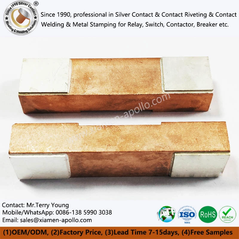
Engineering Loads on Rail Transit DC Contactor Parts
High-Voltage DC Switching and Arc Energy
DC switching presents a different interruption challenge from AC switching because the current does not naturally pass through zero twice per cycle. Once an arc forms between separating contacts, the contactor must generate sufficient opposing voltage and use its magnetic blowout, arc chute, or other arc-control mechanism to interrupt the current.
The relevant engineering variables include:
- Rated operational voltage and current under the applicable IEC 60947-4-1 requirements.
- Prospective short-circuit current and the upstream protective device coordination.
- Electrical endurance under the specified utilization category and switching duty.
- Contact opening speed, contact gap, and arc-control geometry.
- Contact temperature rise and resistance after repeated switching cycles.
Arc energy depends on the instantaneous arc voltage and current over time. Therefore, contact erosion cannot be assessed from rated current alone. A contactor switching a high-current DC circuit under inductive loading may experience substantially different erosion from one operating at the same current under a predominantly resistive load.
For rail traction applications, engineering validation should reproduce the actual circuit inductance, supply voltage, interruption current, and switching sequence wherever practical.
Vibration, Shock, and Mechanical Contact Stability
Rail vehicles expose contactor assemblies to vibration, mechanical shock, and repeated acceleration. These loads can affect terminal joints, contact alignment, spring preload, fasteners, and insulating supports.
| Design variable | Engineering concern | Recommended verification |
|---|---|---|
| Contact alignment | Uneven contact pressure and localized heating | Dimensional inspection and contact-pattern assessment |
| Contact force | Contact bounce, unstable resistance, or excessive wear | Force-displacement measurement |
| Terminal joint | Fatigue cracking or increased joint resistance | Visual inspection, joint resistance measurement, and vibration testing |
| Insulating support | Cracking, displacement, or reduced clearance | Mechanical inspection and insulation testing |
| Fastener retention | Loosening under cyclic loading | Torque verification and application-specific vibration testing |
Applicable railway environmental requirements should be identified from the vehicle or equipment specification. EN 61373 is commonly used for railway rolling-stock equipment vibration and shock testing, but the correct test category and mounting location must be selected for the assembly under evaluation.
The contact assembly should be assessed after vibration testing, not only before it. Post-test measurements can reveal loosened joints, permanent deformation, contact misalignment, and resistance changes that are not apparent during an initial dimensional inspection.

Selecting CuW and AgWC Arc-Resistant Contact Materials
Copper-Tungsten Contacts for Severe Switching Duties
Copper-tungsten is a composite material combining a refractory tungsten skeleton with a conductive copper phase. Tungsten contributes high-temperature stability and resistance to arc-related material loss, while copper supports electrical and thermal conduction.
The material is not a single universal grade. Tungsten content, copper distribution, porosity, manufacturing route, and final density affect conductivity, hardness, thermal transport, and erosion behavior.
Typical engineering considerations include:
- Tungsten fraction: Higher tungsten content generally increases hardness and refractory character but can reduce electrical and thermal conductivity.
- Density and porosity: Residual pores can affect local heating, mechanical integrity, and consistency during repeated arcing.
- Contact geometry: Thickness, edge profile, and contact-face dimensions affect current distribution and arc-root movement.
- Joining compatibility: The contact-to-copper interface must accommodate differences in thermal expansion and the selected joining process.
CuW may be considered for contact tips, arc-resistant inserts, and other components exposed to severe switching conditions. The final grade should be selected using measured properties and switching-test results rather than material name alone.
AgWC Contacts for Arc Erosion Resistance
Silver-tungsten carbide combines a silver-based conductive phase with tungsten carbide particles. Its potential use in high-current switching components depends on the specific composition, microstructure, contact geometry, and electrical duty.
AgWC should not automatically be treated as interchangeable with CuW or conventional silver-tungsten materials. Tungsten carbide has different material characteristics from metallic tungsten, and the selected grade must be evaluated for conductivity, hardness, arc erosion, and joining behavior.
Where AgWC is considered, the engineering review should establish:
- The actual composition and applicable material specification.
- Electrical conductivity and hardness test methods.
- Arc erosion under the intended DC voltage, current, and switching frequency.
- Contact-face damage, transfer, and material loss after endurance testing.
- Compatibility with the copper terminal and selected brazing filler metal.
CuW vs AgWC: Material Selection for DC Contactors
| Property or design factor | CuW contact material | AgWC contact material |
|---|---|---|
| Principal material system | Tungsten and copper composite | Silver and tungsten carbide composite |
| Primary design consideration | Refractory behavior, conduction, and erosion resistance | Silver-phase conduction combined with carbide-related hardness and wear characteristics |
| Electrical conductivity | Depends on tungsten fraction, density, and microstructure | Depends on silver fraction, carbide content, and microstructure |
| Hardness | Composition- and process-dependent | Composition- and process-dependent |
| Arc erosion behavior | Must be verified at the intended switching duty | Must be verified at the intended switching duty |
| Joining requirements | Requires a compatible filler and controlled thermal cycle | Requires a compatible filler and controlled thermal cycle |
| Selection basis | Measured properties and application-specific switching tests | Measured properties and application-specific switching tests |
The table describes material-selection considerations rather than guaranteed numerical rankings. Neither material can be assigned a universal conductivity, hardness, or service-life value without a specified grade and supporting test data.
Contact Material Verification and Traceability
Incoming material control should establish the material identity, composition, batch traceability, and inspection status of each contact lot.
Recommended controls include:
- Supplier material certificates tied to the production batch.
- Chemical composition verification when required by the purchasing specification.
- Density and dimensional checks for sintered or infiltrated contact materials.
- Hardness testing using a method appropriate to the material and specimen geometry.
- Electrical conductivity measurement with a defined test method and temperature.
- Microscopic examination of the contact structure when required for qualification or failure analysis.
ISO 9001-based quality management and IATF 16949-based automotive quality systems may support traceability and process discipline where applicable. However, a supplier's certification does not replace product-specific material verification or switching qualification.
Download Contact Material Spec Sheet
Vacuum Brazing of Large Contacts to Thick Copper Terminals
Joint Design and Filler-Metal Selection
Large arc-resistant contact blocks require a joint that transfers current and mechanical loads while tolerating repeated temperature changes. Vacuum brazing can provide a controlled joining environment, but joint performance depends on surface preparation, filler-metal compatibility, joint clearance, furnace temperature profile, and the thermal characteristics of both components.
Copper and refractory contact materials can differ significantly in thermal expansion and thermal conductivity. These differences create local stress during heating and cooling. The joint design should therefore address the contact footprint, terminal thickness, filler-metal distribution, and the intended operating temperature range.
The joining specification should define:
- Base-material grades and incoming surface condition.
- Filler-metal designation and its compatibility with the contact and copper materials.
- Joint clearance and dimensional tolerances at the brazing temperature.
- Furnace vacuum or atmosphere requirements.
- Heating rate, peak temperature, soak time, and cooling profile.
- Post-braze inspection and electrical acceptance criteria.
Brazing temperatures and clearances must be established for the selected alloy system. A generic furnace recipe should not be applied to every CuW or AgWC grade.
Vacuum Brazing vs Resistance Welding
| Process factor | Vacuum brazing | Resistance welding |
|---|---|---|
| Heat generation | Furnace heating of the assembly or localized controlled heating, depending on the process | Electrical resistance generates heat at the joint |
| Typical joint approach | Filler metal flows through a prepared joint | Base materials are joined through pressure and localized heating, with or without a separate filler |
| Large contact blocks | Can suit large contact inserts and thick copper terminals when joint design permits | Feasibility depends on electrode access, material combination, section thickness, and machine capacity |
| Atmosphere control | Vacuum can limit oxidation during the thermal cycle | Surface condition and local shielding or process control depend on the welding method |
| Thermal exposure | Often involves a comparatively broad thermal cycle | Often more localized, though heat-affected zones remain possible |
| Key process risks | Incomplete wetting, voids, filler displacement, and thermal stress | Incomplete fusion, expulsion, indentation, and inconsistent weld resistance |
| Verification | Joint inspection, cross-section analysis, resistance measurement, and mechanical testing as applicable | Weld monitoring, section analysis, resistance measurement, and mechanical testing as applicable |
Neither process is universally preferable. Resistance welding may be suitable for compatible contact and terminal geometries, while vacuum brazing may be more practical for certain large or thick assemblies. Selection should follow design validation and production capability trials.
3.3 Process Variables That Control Brazed-Joint Quality
Surface preparation
Oxide, oil, machining residue, and other contamination can prevent filler-metal wetting. Cleaning procedures should be defined for the base materials and filler system, with handling controls that prevent recontamination before furnace loading.
Joint clearance
An excessively tight gap can restrict filler flow, while an excessively wide gap can weaken capillary action or produce an unsuitable joint geometry. The allowable clearance should be established from the filler alloy, joint orientation, surface condition, and brazing temperature.
Thermal profile
The assembly must reach a temperature sufficient for filler flow without causing unacceptable base-material changes. Heating and cooling rates should account for component mass, section thickness, thermal conductivity, and differences in expansion.
Filler distribution
Filler displacement, incomplete coverage, or local accumulation can reduce effective bonded area and affect current distribution. Fixtures should maintain alignment without obstructing the intended flow path.
Post-braze inspection
The inspection plan should identify acceptable joint coverage, dimensional change, surface condition, and any permitted discontinuities. Cross-sectional metallography may be required during process qualification or failure analysis.
Electrical and Mechanical Acceptance of Brazed Assemblies
A visually sound joint does not necessarily have low electrical resistance or sufficient mechanical strength. Verification should combine inspection with measurements appropriate to the design.
| Verification item | Purpose | Acceptance basis |
|---|---|---|
| Four-wire joint resistance | Measures the electrical resistance of the defined joint region | Drawing or product specification |
| Dimensional inspection | Checks contact position, terminal geometry, and assembly tolerances | Approved drawing |
| Cross-section examination | Evaluates wetting, voids, and interface condition | Qualified joint criteria |
| Shear or pull testing | Assesses mechanical integrity when the geometry supports a meaningful test | Approved test method and design requirement |
| Thermal cycling | Evaluates resistance stability and damage after temperature changes | Application-specific qualification plan |
| Visual inspection | Identifies surface defects, misalignment, or visible filler irregularities | Approved workmanship criteria |
A shear-strength threshold, such as 150 MPa, should only be stated when it has been established for the actual joint geometry, test method, and acceptance specification. A value taken from an unrelated brazed joint is not a valid universal requirement.

Thermal Shock, Insulation Clearance, and Qualification Testing
Thermal Shock vs Thermal Cycling
Thermal shock and thermal cycling evaluate related but different failure mechanisms. Thermal cycling assesses the effects of repeated temperature changes over defined dwell periods, while thermal shock generally imposes a more abrupt temperature transition.
For a large contact block brazed to a copper terminal, temperature changes can create differential expansion stresses at the joint. Repeated cycles may cause fatigue, microcracking, changes in contact resistance, or progressive separation at a weak interface.
The qualification plan should specify:
- Minimum and maximum temperatures.
- Transition rate or transfer time, where applicable.
- Dwell duration at each temperature.
- Number of cycles.
- Sample quantity and production-lot representation.
- Electrical and mechanical measurements before and after testing.
ASTM B117 is a salt-spray corrosion test method; it is not a thermal shock standard. It may be relevant when corrosion resistance is part of the product qualification, but it cannot substitute for thermal cycling or thermal shock testing.
Insulation Clearance and Creepage Distance
Clearance is the shortest distance through air between conductive parts. Creepage distance is the shortest distance along the surface of an insulating material between conductive parts. Both affect insulation coordination, but they are not interchangeable.
For DC contactor assemblies used in rail transit and renewable energy systems, required distances depend on rated insulation voltage, transient overvoltage, pollution degree, insulating material properties, altitude, and the applicable product standard.
The design review should confirm:
- Rated operational voltage and rated insulation voltage.
- Overvoltage category and applicable transient conditions.
- Pollution degree and insulating material group, where specified.
- Altitude corrections when required by the relevant standard.
- Terminal-to-housing and pole-to-pole distances.
- Insulation test voltage and test duration.
IEC 60664-1 provides insulation-coordination principles for low-voltage systems, while IEC 60947-4-1 addresses electromechanical contactors and motor-starters within its scope. Railway equipment may also require additional product-specific and railway-system requirements.
No universal clearance value should be assigned to every high-voltage DC contactor. The approved design must be evaluated against its voltage rating, insulation system, installation environment, and applicable standards.
Consult Our Electrical Engineers Today
Manufacturing Controls for Heavy-Duty DC Contactor Assemblies
Dimensional Control and Contact Alignment
Contact-face geometry influences the initial contact area, local pressure, current distribution, and wear pattern. The drawing should define the relevant dimensions, datums, flatness, parallelism, and positional tolerances.
A tolerance such as ±0.005 mm may be achievable for certain machined features under suitable conditions, but it should not be applied indiscriminately to large brazed assemblies. Tooling capability, part size, material behavior, inspection method, and functional need determine the appropriate tolerance.
Critical dimensions should be measured using calibrated equipment and a documented inspection plan. Coordinate measuring machines, optical systems, height gauges, and suitable electrical metrology may be used according to the feature being verified.
Production Traceability and Quality Documentation
For rail transit and renewable energy procurement, traceability should connect incoming materials to the finished contactor assembly.
The control plan may include:
- Material grade, supplier, and batch identification.
- Contact composition and inspection records.
- Copper terminal material and dimensional results.
- Brazing batch number and recorded furnace parameters.
- Operator, fixture, and production-lot identification where required.
- Resistance, mechanical, and insulation test records.
- Nonconformance reports and corrective-action documentation.
ISO 9001 and IATF 16949 should be cited only in accordance with the supplier's actual certification status and scope. RoHS and REACH declarations should likewise be based on applicable substance requirements and supporting compliance documentation.
Supplier Qualification for China-Made DC Contactor Components
When qualifying a China-based manufacturer or supplier, procurement teams should assess more than unit price. The review should establish whether the supplier can manufacture the specified contact materials, maintain the brazing process window, measure joint resistance, and support repeatable production.
A supplier assessment can cover:
- Verified manufacturing and inspection capabilities.
- Material sourcing and lot-level traceability.
- Brazing equipment, process monitoring, and maintenance controls.
- Dimensional and electrical measurement capability.
- Sample qualification and engineering-change control.
- Production capacity, delivery planning, and defect-response procedures.
The purchase specification should identify which operations are performed in-house and which are subcontracted. This is particularly important for contact-material production, specialized brazing, surface treatment, and independent testing.

Frequently Asked Questions about Contact Welding
How can buyers verify the brazed-joint quality of high-current DC contactor parts?
Request a documented brazing process specification, material traceability records, dimensional inspection results, four-wire joint-resistance measurements, and representative cross-section or mechanical-test reports. Acceptance limits should be agreed before production qualification.
What information is required to select CuW or AgWC contacts for rail transit DC contactors?
Provide rated DC voltage, continuous and interruption current, load inductance, switching frequency, contact geometry, expected endurance, and thermal limits. The supplier should confirm the proposed grade using material data and application-specific switching tests.
Can a China-based factory supply customized heavy-duty DC contactor assemblies for renewable energy systems?
Yes, subject to the manufacturer's verified material, joining, machining, inspection, and testing capabilities. Buyers should confirm drawing ownership, sample approval procedures, batch traceability, production capacity, and the qualification tests required for the intended application.
contact us
If your rail traction or renewable energy project requires high-current copper terminals, CuW or AgWC arc-resistant contacts, and controlled Contact Joining Brazing, submit your drawings and electrical duty specifications now for a manufacturing-capability review, process assessment, and quotation from a China-based factory.
