The performance of Stainless Steel Sheet Metal Stamping Parts is determined by three key factors: the material grade and its temper (hardness state), die clearance and springback compensation, and post-stamping passivation. Within the common thickness range of 0.3–3.0 mm, grades 304 and 316L satisfy most structural and corrosion-resistance requirements; 301 is used for applications requiring elasticity retention, while 430 is chosen for cost-sensitive decorative components. Defining these parameters during the blueprint review stage establishes a foundation for dimensional stability and batch-to-batch consistency in mass production, setting the stage for further process optimization.
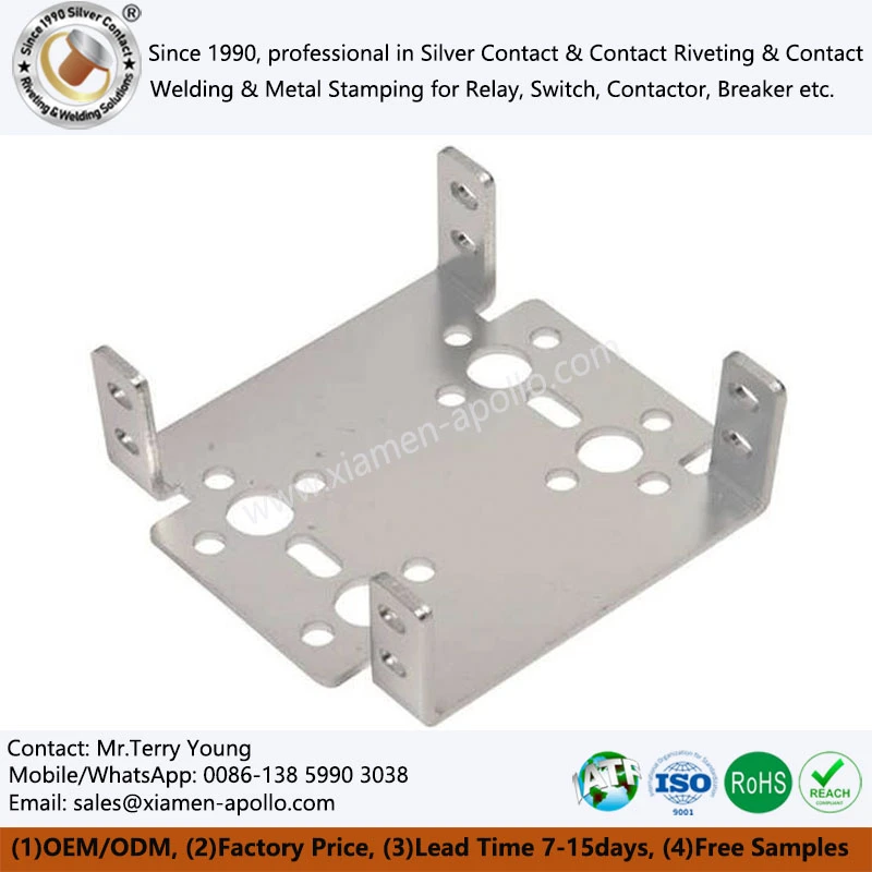
Definition: How 304 Stainless Steel Punchings Are Formed
Stainless steel stamped parts are two- or three-dimensional metal components produced from stainless steel coils or sheets through separation and plastic deformation, achieved using dies in a stamping press. The forming process relies on a combination of four fundamental operations:
- Blanking: Separating the sheet along a closed contour to define the external shape and hole locations in a single step.
- Bending: Folding the sheet around the radii of a die to create angles or curved structures.
- Deep Drawing: Pressing a flat blank into a female die (cavity) to form hollow or complex-shaped cavities.
- Flanging: Creating a localized vertical edge around a hole or along an outer boundary, often to increase thread engagement length or provide positioning for assembly.
These operations are arranged in sequence within a single progressive die, allowing multiple processes to be completed in one press stroke. This is the standard approach for the mass production of complex stainless steel parts.
Material Grade Selection: Defining the Material Before Discussing the Process
The process window for Stainless Steel Sheet Metal Stamping is fundamentally dictated by the material itself. Variations in work-hardening rates, yield-to-tensile ratios, and elongation properties necessitate corresponding adjustments to die clearances and springback compensation. The engineering applications for common grades are as follows:
| Grade | Tensile Strength Reference | Forming Characteristics | Typical Applications |
|---|---|---|---|
| 304 (S30400) | 500–700 MPa | Good elongation, wide forming window, notable work hardening | Home appliance structural parts, shielding cans, brackets, fasteners |
| 316L (S31603) | 480–620 MPa | Molybdenum added, resistant to chloride pitting corrosion, formability close to 304 | Food processing equipment, medical devices, components for chemical service environments |
| 301 (S30100) | Over 1000 MPa after cold work hardening | High yield-to-tensile ratio, large springback, suitable for elastic components | Spring strips, clamps, connector contacts |
| 430 (S43000) | 450–600 MPa | Nickel-free, low cost, ductility lower than 304 | Decorative panels, home appliance inner liners |
| 201 | 600–900 MPa | Low cost, corrosion resistance inferior to 304 | Non-cosmetic parts for dry indoor environments |
One often-overlooked factor is the material's temper (hardness state). For the same material grade, forming performance varies significantly between the soft (annealed) state and the cold-rolled (hard) state. Simply specifying "304" on a drawing is insufficient; the delivery temper and thickness tolerance must also be defined. Otherwise, springback data observed during the trial-run phase cannot be reliably replicated.

Process Boundaries: Capabilities of Four Key Operations
Blanking/Punching: The limits are determined by the minimum hole diameter and the width of narrow slots. As a general rule of thumb, hole diameters should be at least 1.0 times the material thickness, narrow slot widths at least 1.2 times, and the distance from a hole to the outer edge at least 1.5 times the material thickness. Falling below these thresholds significantly compromises punch strength and tool-edge lifespan.
Bending: The limits depend on the internal bend radius and the bend height. The internal radius should generally be at least 0.5 times the material thickness; a radius that is too small can cause cracking on the outer surface. If the bend height is insufficient, springback cannot be controlled via the die radius and must instead be compensated for through a secondary "setting" (coining/re-striking) operation.
Deep Drawing: The limits are governed by the degree of deformation per draw. Because stainless steel work-hardens rapidly, the first draw ratio is typically kept between 0.5 and 0.6, with subsequent draws reducing this value by approximately 0.1 each time. Intermediate annealing stages are mandatory; otherwise, the walls of the drawn part will likely wrinkle or fracture.
Flanging: The limits depend on the ratio of the flange height to the hole diameter. If the flange height exceeds 1.5 times the hole diameter, the material at the hole edge will thin excessively; in such cases, extrusion or multi-stage forming processes should be used instead.
Incorporating these boundaries into a DFM (Design for Manufacturing) review is the most cost-effective step in any Custom Stainless Steel Stamping project. Modifying a design after the dies have already been built typically incurs costs several times higher than making adjustments during the design phase.
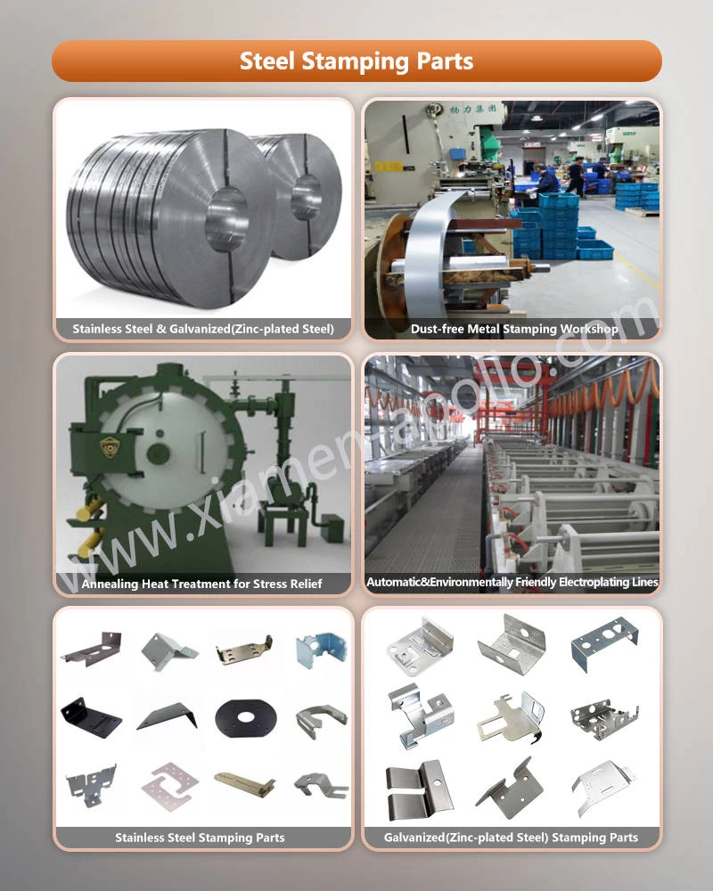
Three Variables Determining Precision Of Stainless Steel Sheet Metal Stamping Sheet
Die Clearance. Due to its high strength and rapid work-hardening, stainless steel requires a slightly larger die clearance than carbon steel. For standard blanking, the clearance is typically set at 8%–12% of the material thickness, whereas for similar parts made of carbon steel, the range is usually 5%–8%. Insufficient clearance accelerates cutting-edge wear and increases blanking force, while excessive clearance reduces the proportion of the burnished zone on the sheared edge and leads to larger burrs. In mass production, the burnished zone is typically required to account for at least 60%–70% of the sheared edge; the clearance must be calibrated based on the specific material grade and thickness.
Springback. Grade 304 stainless steel has a high yield-to-tensile ratio, resulting in significant springback during bending. Strategies to control this include: incorporating overbending compensation into the die radii, adding stiffening ribs (beads) in the bending zone to restrain springback, and introducing a secondary "setting" (coining/calibration) station. Springback compensation data must be established individually for each material grade, thickness, and rolling direction; values cannot be applied across different grades. Angular tolerances are generally maintained within ±0.5°, while for visible (cosmetic) parts, this may be tightened to ±0.3°.
Burrs. Burr height is influenced by clearance, cutting-edge wear, and lubrication conditions. For general structural components, burr height should be kept below 0.05 mm, while for electrical contact surfaces or mating surfaces in assemblies, it should be kept below 0.02 mm. Since cutting-edge wear accumulates with every stroke, scheduling periodic regrinding of the dies-rather than relying on post-process deburring-ensures more consistent quality.
Another issue specific to stainless steel is galling (die pickup). During plastic deformation, stainless steel is prone to cold-welding with the die surface, causing scoring or galling. Countermeasures include using specialized stamping lubricants (containing extreme-pressure additives), applying TiCN or DLC coatings to the die surfaces, and polishing the punch radii to a mirror finish. This is particularly critical for deep-drawn parts made from thick-gauge material, as it directly determines the service life of the tooling.
Consult Our Electrical Engineers Today
Passivation: Surface Treatment Is Not Optional
Blanking and deep drawing disrupt the chromium-rich oxide film on the surface of stainless steel. Sheared edges, the walls of deep-drawn components, and the roots of flanges all serve as potential initiation points for corrosion. The standard process consists of degreasing, followed by pickling or electrolysis, and finally passivation-using a nitric acid or citric acid-based system to regenerate the passive oxide layer. Depending on the intended application, the surface may then undergo further finishing, such as brushing, sandblasting, mirror polishing, or the application of an anti-fingerprint coating.
For components used in food processing equipment or medical devices, surface roughness must be strictly controlled-typically requiring an Ra ≤ 0.8 μm-and care must be taken to ensure no machining oils remain in recessed areas or "dead zones." Salt spray test requirements vary by application: indoor components typically require 48–96 hours of resistance, while parts intended for outdoor or coastal environments must withstand 480 hours or more.
Typical Application Scenarios of Stainless Metal Stamping
Automotive: Exhaust system clamps, seat frames, sensor housings, and structural components for battery packs.
Home Appliances: Washing machine drum supports, cooktop panels, dishwasher liners, and refrigerator door components.
Electronics: Electromagnetic shielding covers, connector housings, and power module brackets.
Photovoltaics (PV) and Energy Storage: Module clamps, rail connectors, and internal linings or mounting plates for energy storage cabinets.
Food and Medical: Hoppers, trays, and instrument stands.

Five Stages of Custom Development
A comprehensive precision stainless steel stamping project typically follows this workflow:
Blueprint Design → DFM (Design for Manufacturing) Review → Die/Mold Fabrication → Trial Stamping and First-Article Inspection (FAI) → Mass Production and Process Control.
The trial stamping phase is the most critical. The first article must undergo full-dimensional inspection, verification of material certification, and measurement of springback; the actual measured angles are compared against the tolerances specified in the blueprints to confirm that the necessary compensation has been applied. Once the first article is approved, a small-batch validation run follows, focusing on dimensional drift and burr formation over continuous stamping cycles. During mass production, Statistical Process Control (SPC) is used to monitor key dimensions, while full traceability is maintained for raw material coil heat numbers, stamping parameters, and surface treatment batches.
Frequently Asked Questions
Q: Can standard carbon steel dies be used for stamping stainless steel parts?
They may be acceptable for short runs or small-batch production, but they are not recommended for mass production. Stainless steel exhibits high resistance to deformation, which causes rapid wear on the cutting edges of standard tool steels and leads to a quick loss of clearance control. For high-volume production, molds are typically constructed using SKD11, DC53, or cemented carbide inserts, often enhanced with surface coatings.
Q: How do you determine if a deep-drawn part requires multiple forming stages?
First, calculate the limiting deformation for a single draw. If the target depth of the component exceeds what can be achieved in the initial draw, the process must be broken down into multiple stages, with an annealing step included between stages to eliminate work hardening.
Q: What are the consequences of a discrepancy between the specified material thickness and the actual thickness tolerance?
It directly affects clearance settings and springback compensation. A material thickness fluctuation of ±0.05 mm can cause an actual shift in blanking clearance of up to 15%, leading to inconsistencies in burr formation and edge quality. Defining the material thickness tolerance range before placing an order is essential for ensuring batch-to-batch consistency.
contact us
If you have a drawing for a Stainless Steel Stamped Part and would like to know whether it can be formed in a single operation, what the appropriate clearance should be, or if a secondary sizing (coining) station is necessary, please send us your STEP or DXF file. Our engineering team will review the drawing and provide DFM (Design for Manufacturing) feedback. With our in-house mold-making facility-capable of producing progressive dies, deep-drawing dies, and dies for thick-gauge materials-we handle all mold maintenance and modifications internally, eliminating the need to wait for external vendors. Simply provide the material thickness, grade, and annual volume, and we will respond with a comprehensive quotation and process plan.