The engineering answer first: Stainless Steel Sheet Metal Stamping Parts are produced by forcing metal to flow plastically inside a hardened die, and the tolerance band that actually matters is set by die clearance, strip feed accuracy and springback compensation, not by press tonnage. On 304 or 316 coil, a correctly built progressive die holds ±0.01 mm on critical features and Ra 0.8 µm on the formed face, with the work-hardening behaviour of austenitic strip absorbed during die tryout instead of being corrected after serial production begins. Everything below is the process logic behind that number.
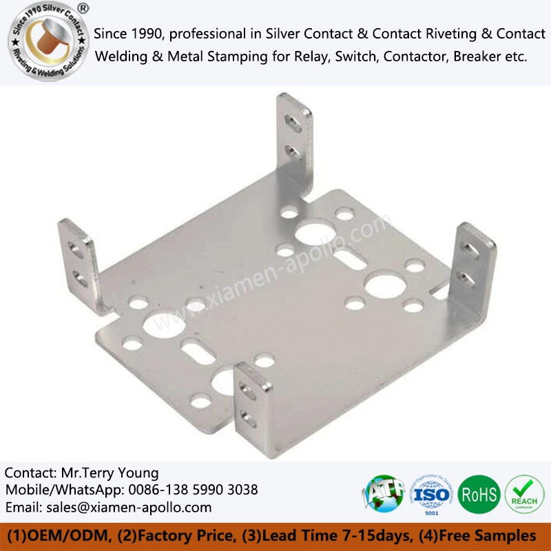
Why stainless behaves differently at the press
Stamping is a plastic deformation process. The punch loads the strip against the die cavity, the material yields, and the Stainless Steel Stamped Part takes the die contour. The load path runs through two stages: an elastic stage, where the sheet stretches and returns to its original shape once the load is removed, and a plastic stage, where deformation becomes permanent and the metal fills the cavity. The dividing line between the two is the yield point of the grade in its current condition, and that is where stainless sheet departs from mild steel.
Austenitic grades such as 304 (roughly 18% chromium, 8% nickel) and 316 (with 2–3% molybdenum added for chloride resistance) harden rapidly as they are cold worked. Every forming station raises the flow stress of the material that passes through it, so a part formed at station five is being cut from strip that already carries the strain history of stations one through four. Mild steel does not drift this way to the same degree. Practical consequences: punch loads climb along the tool, the last forming stations need more press capacity than the first, and the blank must be sequenced so that the heaviest draw does not sit downstream of three or four coining operations.
Springback is the second difference. Austenitic strip recovers more elastically than low-carbon steel at equal strength, and the recovery is anisotropic because the coil carries rolling directionality. A 90° bend designed on nominal geometry will open past 90° once the punch withdraws. Tool designers compensate by over-bending the punch face, by adding a bottoming or coining step at the end of the stroke, or by building the form angle into the die block from FEA output. Ferritic grades such as 430 behave closer to carbon steel and need less compensation, which is one reason the grade choice belongs in the DFM conversation and not in the purchasing spreadsheet alone.
Galling is the third. Stainless has a strong tendency to adhesive wear against tool steel, because the passive chromium oxide layer breaks down under high contact pressure and fresh metal welds to the punch face. Once a smear starts, it grows: the welded layer picks up more material each stroke, surface finish degrades, and eventually the punch scores the part. Control comes from three places at once: a polished or coated punch surface, a lubricant that maintains a film under high unit pressure, and a die clearance wide enough that the punch is not shaving the wall on the way down.
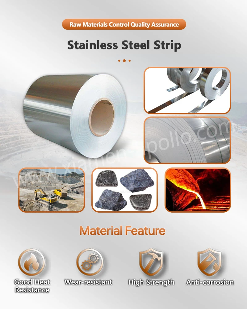
Die architecture: single-station and progressive
Two architectures cover most of this work. Single-station tooling completes one operation per stroke: blank, then bend, then pierce, with the part transferred between tools or between manually loaded stations. It suits low volume, thick gauge, or geometries where the draw direction changes. Progressive tooling carries the strip through a sequence of stations in one die, with the carrier web advancing by a fixed pitch each stroke, and completes piercing, trimming, bending, drawing and forming before the OEM stainless steel stamping part is cut free at the last station.
Progressive dies are the default for connector shells, relay cores, contact carriers and thin enclosure parts, because one die replaces four or five separate operations and the part never leaves the tool between steps, so the locator is the strip itself rather than a re-clamped fixture. The cost sits in the tool: a progressive die carries more stations, more maintenance points and a longer debug cycle. The volume threshold at which progressive tooling pays back is a function of station count, tool life and changeover cost, and it is worth calculating per part rather than assuming.
What the architecture does not change is the accuracy chain. Tolerance on a stamped feature is the sum of die manufacturing tolerance, punch-to-die alignment, strip feed pitch error, coil gauge variation and springback residual. Reducing the first three gets a tool that is capable at tryout; the last two decide whether it stays capable across a million strokes. This is why ±0.01 mm is quoted against a defined feature set and a defined strip specification, not as a blanket figure for every dimension on the drawing.
Consult Our Electrical Engineers Today
The variables that hold ±0.01 mm
Clearance is the first lever. It is set as a percentage of sheet thickness, and the percentage runs wider for austenitic grades than for mild steel because a tight clearance on work-hardening strip loads the punch edge, accelerates wear and pushes burr height up. Too wide, and the cut edge rolls instead of shearing, leaving a ragged break face. Clearance is a per-grade, per-thickness decision, and it is the first item to check when a transferred tool starts drifting.
Blank-holder and counter-pressure control is the second. Stainless draws need a hold-down force high enough to stop the flange from flowing into the cavity, and a counter-pad on the reverse side to keep the drawn wall from thinning at the punch nose. Under-held flanges wrinkle, over-held flanges starve the cavity and the wall tears. On a servo press the ram profile can be programmed - slow contact, controlled draw speed, dwell at bottom - which reduces the shock load that drives both tearing and galling.
Strip feed and pilot accuracy is the third. Progressive work locates on pilots that engage before the tools cut, so pitch error and strip camber convert directly into position error on the part. 304 Stainless Steel Punching shares similar feed control challenges alongside 316. Servo feeders with closed-loop pitch correction hold this in check; mechanical roll feeds on wide coil do not, particularly on 316 where the higher strength resists straightening.
Tool wear management is the fourth. Punch and die edges are consumables. Once the edge radius grows past the point where the shear zone turns into a burnish zone, burr height climbs, and burr height is a functional defect on contact and connector parts, not a cosmetic one. Scheduled edge inspection, a register of stroke counts per tool, and a resharpening interval set from measured burr rather than from calendar time keep the last stroke as capable as the first.
Surface integrity and post-stamp finishing
Ra 0.8 µm on a formed face is achievable with a polished die cavity and a lubricant that holds a film through the draw. It is not achievable with a tool that has started to gall, whatever the lubricant. Water-based lubricants are increasingly used where the downstream process allows them: they are easier to clean, they cut VOC load in the plant, and they remove the chlorinated paraffin residue that interferes with subsequent welding or brazing. The trade-off is film strength under high unit pressure, which is why heavy draws on 316 often still need a drawing oil with EP additives.
Burr is controlled at the die, then corrected if the drawing demands it. Deburring by vibratory finishing, brush or electrochemical methods removes the rolled edge but also changes the dimension at the cut face, so the allowance has to be designed in rather than added later.
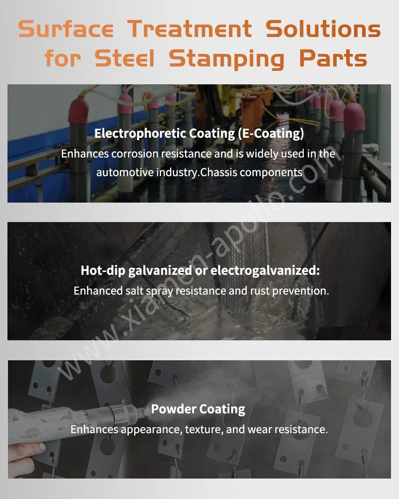
Passivation matters on 304 and 316, where the Stainless Steel Sheet Metal Stamping Sheet sees moisture, chloride or repeated cleaning. Cutting and forming disrupt the passive layer and leave embedded iron from tool contact; a nitric or citric passivation step per a recognized specification restores the oxide film. Salt-spray duration should be written into the drawing as a test method and an acceptance hour count agreed between buyer and supplier, because the grade, the surface finish and the passivation batch all move the result.
Where these parts land
In low-voltage switchgear, Stamped Stainless Parts appear as arc chute supports, terminal hardware, spring carriers and housing components where the part must hold shape at elevated temperature and resist corrosion in humid cabinets. Relay cores and pole pieces are stamped and annealed to control magnetic properties, then assembled with silver contact material by brazing or welding; the stamping tolerance on the contact seat drives contact gap consistency across the batch.
In EV and high-voltage DC hardware, the same process produces contactor housings, coil formers, shielding cans, busbar supports and battery-pack brackets. The functional requirements shift: flatness and position tolerance on the mounting face, controlled burr on current-carrying edges to avoid field concentration, and repeatable wall thickness on drawn enclosures that must seal. Stainless is chosen here for corrosion resistance in the presence of electrolyte and for retained strength at the temperatures reached near power terminals.
In electronics and instrumentation, thin-gauge stamping delivers shielding cans, connector shells and sensor housings where wall thickness is the weight budget and the die is the only way to hold hole pitch at the tolerance the signal path requires.

contact us
Send the Stainless Steel Sheet Metal Stamping Parts drawing set, the grade callout and the annual volume, and the tool concept, the station sequence and the tolerance capability statement come back with the quotation - including the features where ±0.01 mm is realistic and the ones where the geometry will not hold it. DFM feedback is returned within two working days, and a first-article report with dimensional layout and material certification ships with the first production lot.