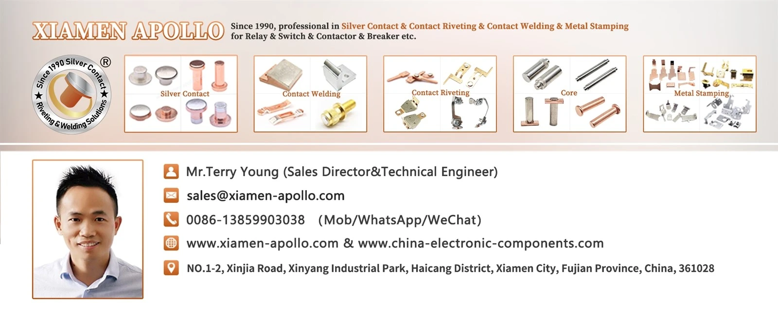
Aluminum Photovoltaic Bracket Accessories transfer mechanical loads between photovoltaic modules, rails, roof attachments, and supporting structures. Their service life depends on alloy temper, section geometry, hole-position accuracy, fastener preload, surface treatment, and resistance to environmental corrosion. Selecting 6063-T5 or 6061-T6 aluminum is only the starting point: each component must be verified against its intended load path, installation conditions, and project-specific design requirements.
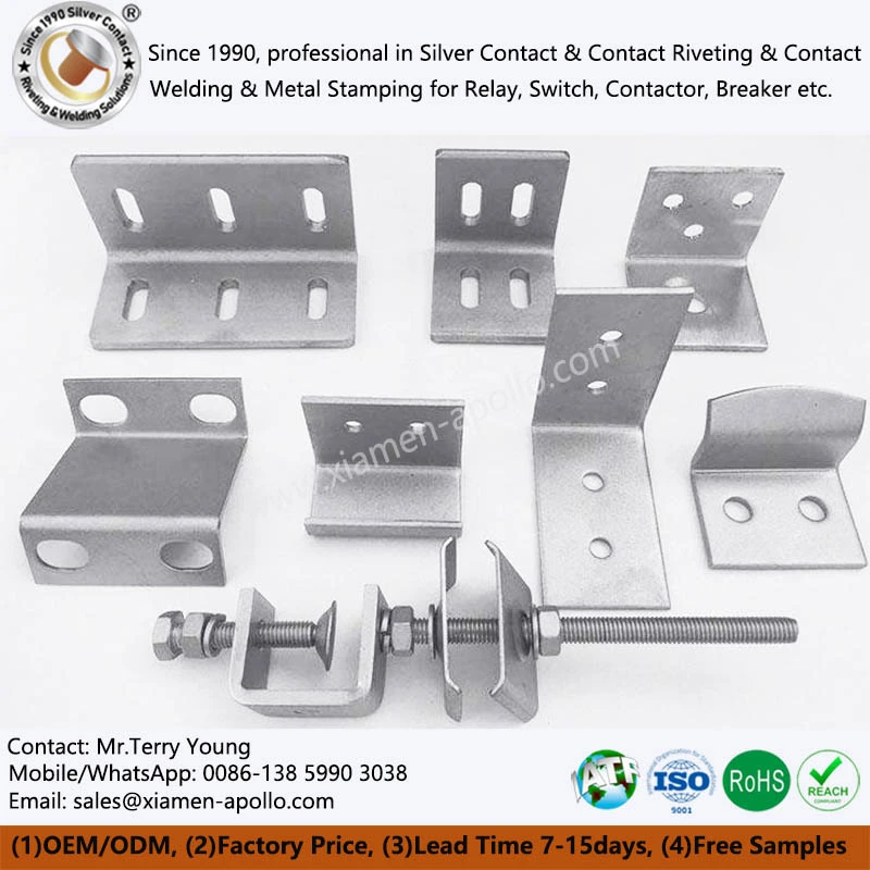
Structural Function and Engineering Requirements for Aluminum Mounting Brackets
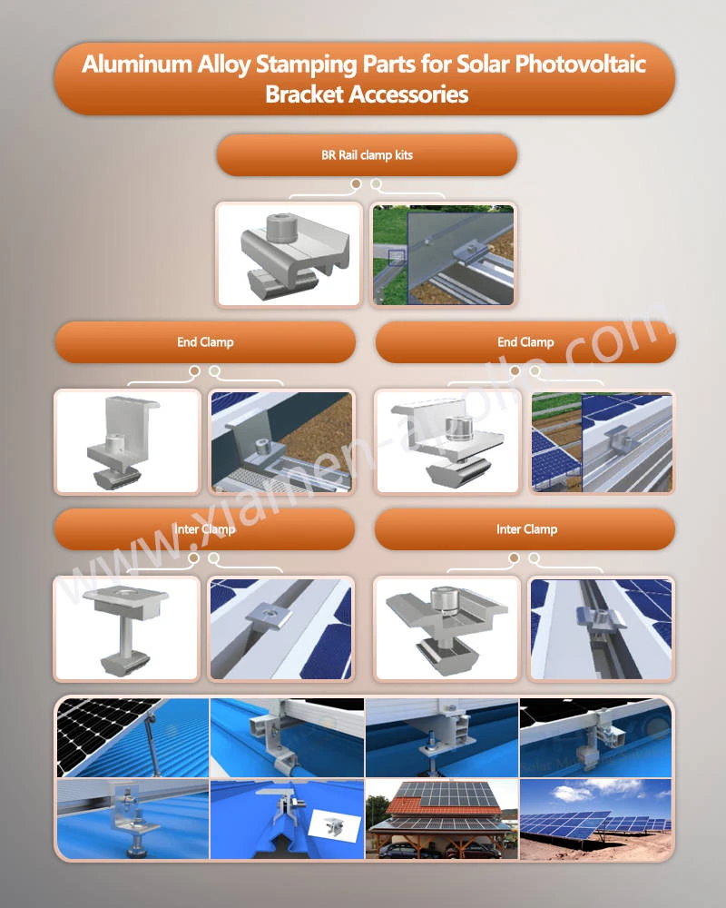
Photovoltaic mounting hardware includes rail connectors, end clamps, mid clamps, roof hooks, brackets, splice plates, and fastener interfaces. These components restrain module movement and transfer wind uplift, downward snow pressure, and other mechanical loads into the roof or supporting frame.
Load transfer and failure modes under IEC 61215 and project design criteria
A mounting accessory should be assessed as part of the complete assembly rather than as an isolated aluminum part. Typical failure modes include local yielding around bolt holes, clamp slippage, bearing deformation, section bending, thread stripping, and fatigue cracking under repeated wind-induced loading.
| Component | Primary mechanical function | Main inspection concern |
|---|---|---|
| Aluminum end clamp | Retains the outer edge of a PV module | Clamp engagement and contact pressure |
| Aluminum mid clamp | Secures adjacent module frames | Grip geometry and frame compatibility |
| Roof clamp hook | Transfers rail loads to roof attachments | Hook deformation and connection strength |
| Rail connector or splice | Joins adjacent aluminum rails | Joint stiffness and alignment |
| Waterproof solar rail | Supports modules while managing designed drainage interfaces | Section strength, joint sealing, and drainage geometry |
IEC 61215 addresses photovoltaic module design qualification and type approval; it is not, by itself, a complete structural certification for every mounting accessory. Structural load calculations, applicable building codes, and the mounting-system manufacturer's installation requirements must also be considered.
Dimensional control for ±0.10 mm or tighter interfaces
Hole spacing, slot width, hook curvature, rail engagement depth, and clamping-face flatness determine whether an accessory fits its mating parts. A general-purpose stamped component may use a drawing tolerance of ±0.10 mm, while a critical locating feature may require ±0.05 mm or tighter. These are illustrative targets, not universal requirements; the final tolerance must reflect the assembly design, process capability, and measurement method.
Hole position: Specify the datum scheme and positional tolerance on the engineering drawing.
Burr height: Define a maximum acceptable burr based on hand safety, coating integrity, and mating-surface contact.
Contact surfaces: Control flatness and edge condition where clamp force is transferred to the module frame.
Rail interfaces: Verify the fit across extrusion profiles, connectors, and roof attachments.
Aluminum Stamping, Deburring, and Surface Treatment Process Control
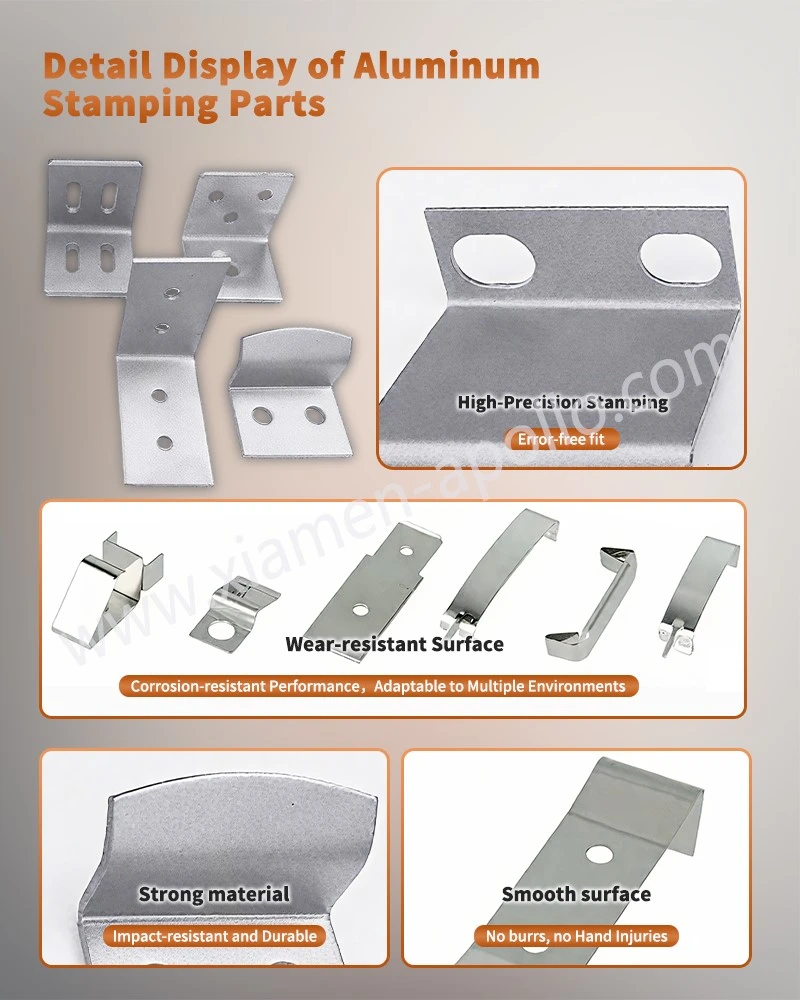
The manufacturing route for Aluminum Alloy Solar Panel Mounting Brackets commonly combines coil or strip preparation, progressive die stamping, secondary forming, deburring, cleaning, surface finishing, and dimensional inspection. Extruded rails and complex profile sections may require extrusion, cutting, drilling, or CNC machining instead of stamping. The process must match the part geometry rather than forcing every component into a single production method.
Progressive die stamping and hole-position accuracy
Progressive die stamping can combine piercing, notching, forming, and cutoff operations in a controlled production sequence. The finished tolerance depends on alloy temper, sheet thickness, die clearance, punch wear, press stability, and springback after forming.
| Process variable | Engineering effect | Recommended control |
|---|---|---|
| Sheet thickness | Affects stiffness, forming load, and hole-edge quality | Incoming thickness inspection and material certificates |
| Die clearance | Influences burr formation and cut-edge condition | Validate against alloy and thickness; inspect wear |
| Punch wear | Can increase burr height and dimensional drift | Defined inspection intervals and tool-life tracking |
| Forming radius | Affects cracking risk and dimensional recovery | Verify against alloy temper and bend orientation |
| Springback | Changes final angles and hook geometry | First-article measurement and compensation trials |
| Part location | Determines repeatability between features | Datum-based gauges and coordinate measurement where needed |
Tolerance capability should be established using first-article inspection and production-run data. A nominal tolerance on a drawing does not automatically demonstrate process capability.
Burr removal, edge quality, and coating adhesion
Burrs around pierced holes can interfere with assembly, damage protective coatings, and concentrate stress at loaded interfaces. Deburring methods may include brushing, tumbling, abrasive finishing, or dedicated tooling, depending on the part geometry and required edge condition.
The objective is not simply to remove visible sharp edges. Excessive deburring can round critical contact surfaces, enlarge openings, or reduce local engagement depth. After deburring, inspect critical hole dimensions and confirm that the selected cleaning process removes residual abrasive and lubricant before coating.
Anodizing, powder coating, and corrosion-resistant surface finishing
Anodizing creates an oxide layer on aluminum, while powder coating provides an organic protective and decorative film. Neither process should be selected on appearance alone: film thickness, pretreatment, edge coverage, drainage, electrical isolation, and contact requirements must be evaluated.
| Surface treatment | Main function | Engineering considerations |
|---|---|---|
| Sulfuric acid anodizing | Forms an aluminum oxide layer | Specify thickness, sealing, appearance, and dimensional allowance |
| Powder coating | Provides a colored protective film | Control pretreatment, film thickness, adhesion, and edge coverage |
| Chemical conversion treatment | Supports corrosion protection and coating adhesion | Specify chemistry and applicable restricted-substance requirements |
| Uncoated aluminum | Avoids a coating layer at selected interfaces | Evaluate natural oxidation, galvanic compatibility, and environmental exposure |
Anodized or painted surfaces can affect electrical bonding and fastener friction. If the mounting design relies on metal-to-metal electrical continuity, define the bonding interface separately and verify it after surface treatment.
Salt spray testing under ASTM B117 and coating acceptance criteria
ASTM B117 describes a controlled salt spray testing method. The test duration, specimen preparation, scribe requirements, evaluation criteria, and acceptance limits must be specified in the purchase specification or project test plan. A salt spray result does not directly establish a fixed number of outdoor service years.
For coastal installations, testing should consider the complete coating system, cut edges, pierced holes, fastener interfaces, and any areas where the coating is damaged during installation. Where long-term field exposure is the primary concern, supplement laboratory testing with material compatibility review and project-specific environmental assessment.
Download Contact Material Spec Sheet
Aluminum Alloy Selection: 6063-T5 vs. 6061-T6
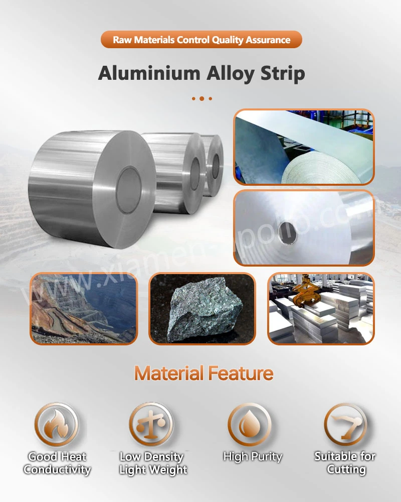
Alloy selection determines the balance between extrusion performance, strength, formability, corrosion behavior, and machining requirements. For photovoltaic mounting systems, the correct grade depends on whether the part is a long structural rail, a machined connector, a stamped clamp, or a formed roof hook.
6063-T5 aluminum for photovoltaic rails and architectural profiles
6063 is commonly selected for extruded aluminum profiles because of its extrusion characteristics and suitability for architectural surface finishing. The T5 temper indicates cooling from an elevated-temperature shaping process followed by artificial aging. It is frequently considered for solar rails, profile connectors, and components with complex cross-sections.
The engineering review should cover actual wall thickness, cross-sectional geometry, extrusion quality, local fastener loads, and the mechanical properties required by the design. Thin rail walls can govern local bearing or bending performance even when the bulk alloy meets its specified strength.
6061-T6 aluminum for higher-strength brackets and machined parts
6061-T6 is often considered where higher strength, machining capability, or load-bearing requirements take priority. The T6 temper generally involves solution heat treatment followed by artificial aging. However, a T6 designation does not guarantee a single tensile or yield strength for every product form and thickness.
| Selection factor | 6063-T5 | 6061-T6 |
|---|---|---|
| Typical product form | Extruded rails and profiles | Machined brackets, structural connectors, selected formed parts |
| Common design priority | Profile complexity and surface finish | Strength and machining performance |
| Manufacturing consideration | Extrusion geometry and wall-thickness uniformity | Machining stock, tool wear, and temper retention |
| Required verification | Applicable product-form material standard and mill certificate | Applicable product-form material standard and mill certificate |
| Key design risk | Local deformation in thin sections | Cracking during forming or property changes after thermal processing |
These are typical selection tendencies, not absolute restrictions. Both grades must be evaluated against the applicable material specification, product form, temper, and actual load requirements.
Artificial aging, alloy chemistry, and incoming material traceability
Mechanical properties depend on alloy composition, heat treatment, product form, and section thickness. Incoming inspection should verify the material grade and temper against the purchase order, with mill certificates traceable to the production lot.
For critical structural parts, verify tensile strength, yield strength, elongation, and hardness using the applicable test methods and acceptance limits. Hardness can support process verification, but it should not replace tensile testing where the design specification requires tensile or yield properties.
Galvanic compatibility between aluminum, stainless steel, and carbon steel
Aluminum accessories are often assembled with stainless steel or carbon steel fasteners. In the presence of moisture and conductive contamination, dissimilar metals can form a galvanic couple, accelerating corrosion of the less noble metal under suitable conditions.
The design review should consider fastener grade, coating system, water retention, electrical isolation, drainage, and maintenance access. Use insulating washers or compatible barrier materials where required by the design, while checking that the selected interface does not compromise clamp preload or structural strength.
Custom Die Development and OEM Dimensional Control
Custom Aluminum Wall Brackets may require new stamping dies, forming tools, machining fixtures, or profile-specific inspection gauges. Tooling development should begin with the functional interfaces and load-bearing geometry rather than the external appearance alone.
Drawing review and tooling feasibility
Before die construction, review the 2D engineering drawing, 3D CAD model, alloy and temper, material thickness, burr direction, bend radii, datum scheme, surface finish, and critical-to-quality dimensions.
For stamped components, check whether hole-to-edge distances and bend geometry are compatible with the selected material and process. For extruded rails, confirm that profile geometry, minimum wall thickness, connector engagement, and drainage features can be produced consistently.
Prototype validation and first-article inspection
The first-article inspection should confirm all designated critical dimensions and functional interfaces. Depending on the component, the validation plan may include:
- Dimensional inspection of hole positions, slots, angles, and section thickness.
- Assembly checks using the specified rail, module frame, clamp, and fasteners.
- Material verification against the specified alloy and temper.
- Surface-treatment inspection for thickness, appearance, and adhesion where applicable.
- Mechanical testing based on the component's load-bearing function.
Prototype approval should be based on recorded results and defined acceptance criteria. Visual confirmation alone is insufficient for dimensions that determine structural fit or load transfer.
Tool maintenance and production repeatability under ISO 9001
Progressive dies and forming tools experience wear that can alter hole size, burr height, bend angle, and part-to-part repeatability. A controlled maintenance plan should define tool-life monitoring, inspection frequency, repair criteria, and approval requirements after die modification.
ISO 9001 provides a quality management system framework. Certification does not itself prove that a specific component meets every drawing requirement. Buyers should review inspection records, nonconformance controls, material traceability, and the manufacturer's ability to maintain the agreed specification over the production lot.
Customization for BIPV and project-specific mounting systems
Building-integrated photovoltaics (BIPV) can impose additional constraints on visible surfaces, color matching, drainage, thermal movement, and integration with building envelopes.
Customization may include:
- Profile cross-section and rail length.
- Hole patterns, slots, and mounting interfaces.
- Clamp geometry for specific module frame dimensions.
- Anodized finishes or powder-coating colors.
- Drainage channels and waterproofing interfaces.
- Packaging and identification for project-specific installation sequences.
Any change to the load-bearing section, fastener interface, or clamp engagement should trigger a design review. Cosmetic changes may also require validation if they affect coating thickness, dimensional fit, or outdoor durability.
Consult Our Electrical Engineers Today
Installation Controls: Fastener Torque, Clamp Grip, and Waterproofing
A dimensionally compliant accessory can still fail when installed with incorrect fasteners, excessive or insufficient torque, unsuitable contact surfaces, or inadequate drainage. Installation instructions should therefore be treated as part of the component's engineering specification.
Fastener torque and preload control
The recommended tightening torque depends on fastener diameter, strength class, thread condition, lubrication, washer arrangement, and the design's required preload. A universal torque value should not be applied across different fastener and clamp combinations.
| Installation variable | Potential consequence | Control measure |
|---|---|---|
| Excessive tightening torque | Thread damage, clamp deformation, or frame damage | Follow the approved torque specification |
| Insufficient tightening torque | Clamp slippage under load or vibration | Use a calibrated torque tool and defined inspection process |
| Incorrect washer arrangement | Uneven contact pressure or local surface damage | Match the approved assembly drawing |
| Contaminated or lubricated threads | Changes in torque-to-preload relationship | Define the permitted thread condition |
| Incompatible fastener material | Galvanic corrosion or premature degradation | Review material compatibility and coating |
Where structural safety depends on a minimum clamp force, torque should be treated as an installation control rather than a direct measurement of clamp force. Validate the torque procedure against the actual fastener and assembly configuration.
Anti-slip geometry and module frame compatibility
Clamp performance depends on the engagement depth, contact-face geometry, surface condition, fastener preload, and compatibility with the module manufacturer's permitted clamping zones. Serrations or textured contact surfaces may increase resistance to sliding, but they can also damage frame coatings or concentrate stress.
The assembly must be checked against the module installation manual. Clamp dimensions and tightening locations should not obstruct drainage channels, damage the module frame, or exceed the permitted frame loading.
Waterproof aluminum solar rail design and drainage
An aluminum alloy waterproof solar rail must be evaluated as part of the roof's complete water-management design. The term "waterproof" should not be interpreted as a guarantee that a rail alone prevents all water ingress.
Review the overlap between rail sections, gasket compression, fastener penetrations, drainage slope, thermal expansion, and the interface with roof membranes or flashing. Water traps and unsealed penetrations can increase corrosion risk and cause leakage even when the rail itself meets dimensional requirements.
Thermal expansion and long-term joint movement
Aluminum expands and contracts with temperature changes. Long rail systems therefore require appropriate allowance for thermal movement, connector behavior, and fixed-point or sliding-point arrangements.
Joint design should account for the expected temperature range, rail length, support spacing, and the mounting-system manufacturer's instructions. Over-constrained rails can transfer unintended loads into clamps, fasteners, or roof attachments.
Frequently Asked Questions
1. How should buyers verify the corrosion resistance of aluminum photovoltaic bracket accessories?
Request the surface-treatment specification, coating-thickness results where applicable, and a salt spray report identifying the test method, exposure duration, specimen preparation, and acceptance criteria. ASTM B117 defines a test method; the project specification must define what constitutes an acceptable result.
2. What information is required to quote custom aluminum solar mounting accessories?
Provide the 2D drawing or 3D CAD file, alloy and temper, material thickness, annual demand, expected order quantity, surface finish, critical tolerances, and required test reports. Also identify the mating module frame, rail profile, fasteners, and installation environment.
3. How can buyers confirm material traceability and quality-system compliance?
Request lot-linked material certificates, dimensional inspection reports, surface-treatment records, and applicable quality-system certificates. Confirm that the certificate scope and validity match the manufacturing site and contractual requirements. ISO 9001 or IATF 16949 certification does not replace product-specific inspection and testing.
contact us
Submit your drawings, alloy requirements, annual volume, and corrosion-test criteria for a manufacturing feasibility review. A qualified aluminum stamping and machining partner should confirm tooling requirements, achievable tolerances, surface-treatment options, inspection methods, and production capacity before quotation approval.