A Brazed Silver Contact Assembly combines a silver-based contact head with a copper support through a metallurgically bonded brazing layer. For high-current circuit breakers, contact material selection, brazing temperature, joint geometry, bond-area coverage, and post-braze inspection directly affect contact resistance, thermal rise, mechanical retention, and arc-erosion behavior.
For MCCB and other high-current switching structures, the engineering target is not simply a silver-rich contact surface. The complete assembly must maintain a low-resistance current path while resisting repeated arc energy, thermal cycling, and mechanical loading at the contact interface.
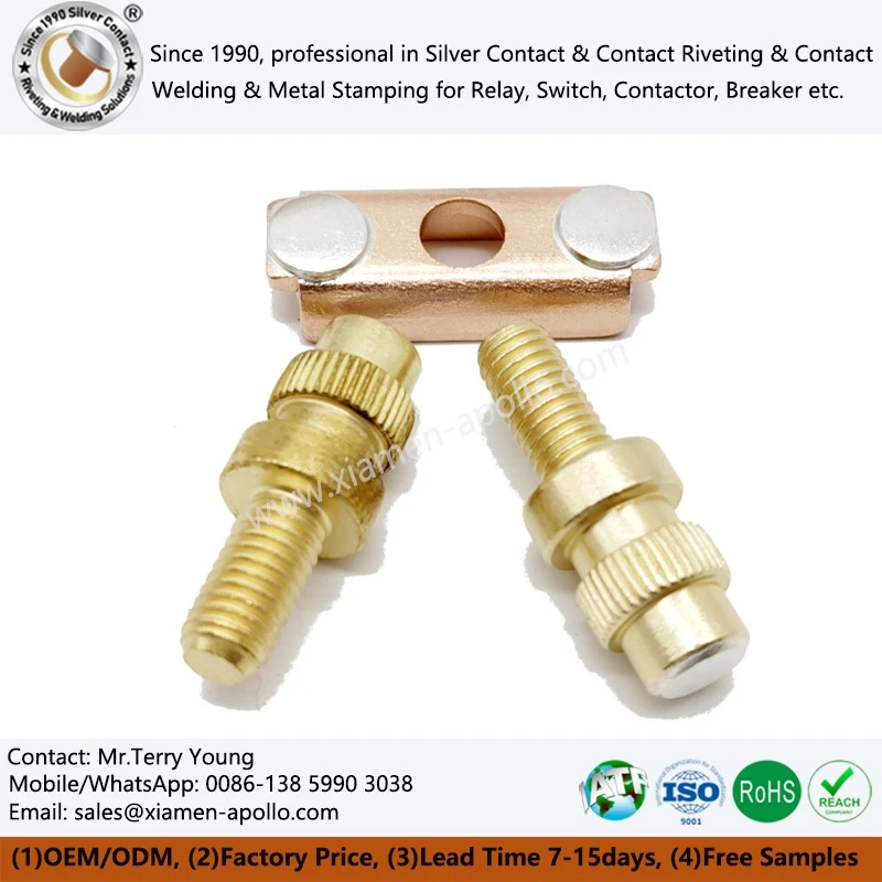
MCCB Arc Erosion: IEC 60947-2 and High-Current Switching Loads
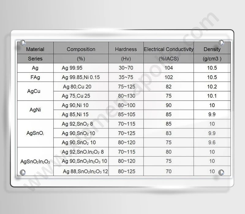
AgWC and AgC Contact Materials for Arc Exposure
During interruption, the contact surface is exposed to localized heating, arc attachment, material transfer and repeated thermal cycling. AgWC and AgC systems are therefore considered when the application requires a harder contact phase than pure silver.
The actual formulation should be selected according to rated current, voltage, short-circuit interruption duty, switching frequency and contact geometry rather than by material name alone.
| Contact system | Main material characteristic | Typical engineering consideration | Suitable evaluation |
|---|---|---|---|
| AgWC | Silver matrix with tungsten carbide phase | Higher resistance to mechanical wear and arc-related material loss | Arc erosion, hardness, contact resistance |
| AgC | Silver-carbon composite | Arc behavior and material transfer must be evaluated against duty cycle | Arc erosion, welding tendency, resistance |
| Pure Ag | High electrical and thermal conductivity | Lower hardness and greater sensitivity to severe arc conditions | Contact resistance, thermal rise |
| AgSnO₂ | Silver matrix with oxide reinforcement | Common in switching applications requiring arc resistance | Welding, erosion, temperature rise |
For an MCCB contact system, the contact head cannot be evaluated independently from the copper support. A contact material with good arc resistance can still produce premature assembly failure if the brazed interface contains voids, insufficient wetting or inadequate bond area.
Contact Resistance and Thermal Rise at IEC 60947 Test Conditions
Contact resistance is affected by surface condition, contact pressure, material hardness, contact geometry and current path design. A low initial resistance value is useful only when it remains stable after thermal and electrical cycling.
For production control, engineering teams should define measurable acceptance criteria for:
- Contact resistance in mΩ under the specified test current.
- Contact temperature rise under the rated current.
- Contact-head dimensional tolerance in mm.
- Brazed joint coverage and detectable void area.
- Mechanical shear strength in MPa.
- Surface hardness or micro-hardness in HV where applicable.
A supplier specification should therefore identify the test method, measurement location, applied current and acceptance limit rather than reporting only a general statement such as "low resistance."
Brazing vs. Riveting: 150 MPa-Class Joint Evaluation and Process Control
Brazed Joint vs. Riveted Joint for High-Current Contacts
Brazing and riveting create different mechanical and electrical interfaces. A riveted contact depends on mechanical deformation and controlled contact between the components, while brazing forms a metallurgical joint through a brazing filler alloy.
| Parameter | Brazed silver contact assembly | Riveted contact assembly |
|---|---|---|
| Joining mechanism | Metallurgical bonding through filler alloy | Mechanical deformation and interference |
| Current path | Contact head → braze layer → copper support | Contact head → rivet/parent material interface |
| Main process variables | Temperature, atmosphere, filler distribution, wetting | Rivet force, stroke, head geometry, alignment |
| Typical inspection | X-ray/CT, ultrasonic, metallographic section | Dimensional inspection, pull/shear testing |
| Void control | Required within specified acceptance criteria | Not normally evaluated as a brazed interface |
| Thermal cycling | Joint integrity must remain stable | Mechanical preload must remain stable |
| Automation | Furnace, induction or high-frequency brazing | Progressive/in-die riveting |
| Typical application focus | High-current breaker and contact assemblies | Relay, contactor and switching components |
A brazed structure can provide a continuous bonded area beneath the contact head, but only when the joint is properly designed. The supplier should control braze clearance, filler-metal distribution, heating rate, peak temperature and cooling conditions.
For riveting, the primary variables shift toward rivet shank diameter, upsetting force, head height, concentricity and residual mechanical preload.
Brazing Temperature, Wetting and Joint Clearance
The brazing process should be established from the actual filler-metal system rather than from a generic furnace temperature.
Important process variables include:
- Filler alloy melting range and liquidus temperature.
- Copper-support surface condition before brazing.
- Contact-head and support alignment.
- Joint clearance and capillary flow distance.
- Heating rate and peak temperature.
- Holding time at brazing temperature.
- Protective atmosphere or vacuum condition.
- Cooling rate and distortion control.
For production qualification, metallographic cross-sections should be used to confirm that the filler alloy has flowed through the intended bonding region without excessive voiding, incomplete wetting or uncontrolled intermetallic formation.
Shear Strength ≥150 MPa: Test Design Rather Than Marketing Claims
A shear-strength value such as ≥150 MPa should only be stated when it is tied to a defined material combination, joint geometry and test method. The numerical result can change significantly with contact-head diameter, braze thickness, overlap area, specimen preparation and loading direction.
For supplier qualification, the test record should identify:
| Test item | Required record |
|---|---|
| Contact material | AgWC, AgC or specified grade |
| Support material | Copper grade and temper |
| Joint area | Measured bonding area |
| Filler metal | Grade/batch identification |
| Test direction | Defined shear-loading direction |
| Maximum load | N |
| Calculated shear stress | MPa |
| Failure location | Interface/filler/parent material |
| Sampling plan | Lot and quantity defined by quality agreement |
A joint that fails inside the parent material rather than along the brazed interface provides different engineering information from an interface failure. QA records should therefore document the fracture location, not only the peak load.
Download Contact Material Spec Sheet
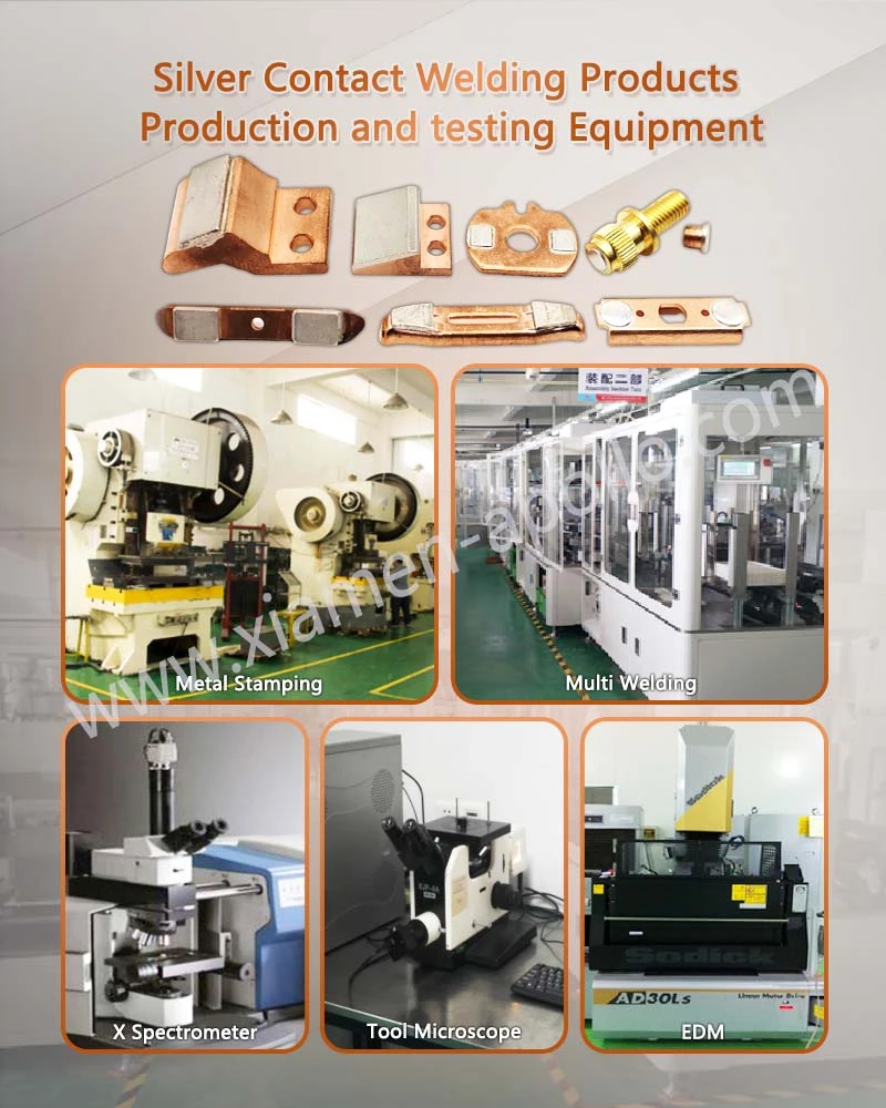
AgWC/AgC Contact Heads on Copper Supports: ≥85% IACS Current Paths
Copper Support Geometry and Electrical Conductivity
The copper support provides the main current-carrying path behind the contact head. Copper grade, cross-sectional area, support thickness, and braze-zone geometry all influence voltage drop and thermal rise.
Where electrical conductivity is specified, the purchase specification should identify the copper grade and test basis. A value such as ≥85% IACS should not be transferred between copper grades without verification.
The mechanical design should also prevent excessive thermal concentration around the brazed area. Sharp section changes, thin support sections, and poorly controlled braze footprints can create local temperature gradients during high-current operation.
AgWC/AgC Interface Design: 0.01–0.05 mm Dimensional Control
The contact head and copper support must remain aligned throughout brazing. Depending on component size and process capability, critical dimensions may be controlled within ranges such as ±0.01 mm to ±0.05 mm, but the actual tolerance must be established from the breaker design drawing and assembly stack-up.
Key dimensions normally include:
- Contact-head diameter.
- Contact-head thickness.
- Support width and thickness.
- Brazing-area diameter.
- Contact-face flatness.
- Concentricity between contact head and support.
- Finished assembly height.
Dimensional inspection should be performed after brazing because thermal distortion can change the final geometry.
Brazing Defects: Voids, Non-Wetting and Misalignment
The most important brazing defects are generally associated with incomplete filler flow, gas entrapment, contamination, and uncontrolled heating.
|
Defect |
Typical cause | Potential effect | Recommended control |
|---|---|---|---|
| Large internal void | Gas entrapment or poor filler flow | Reduced effective bonding area | X-ray/CT inspection |
| Non-wetting | Oxide or surface contamination | Weak interface | Surface preparation and wetting control |
| Excessive filler | Incorrect filler volume | Dimensional variation | Preform/dispensing control |
| Insufficient filler | Incomplete coverage | Localized current and stress concentration | Filler-volume verification |
| Misalignment | Fixture movement | Contact-position error | Precision fixture and CMM |
| Thermal distortion | Excessive heat input | Flatness/height deviation | Thermal profile control |
A controlled brazing process should therefore be combined with dimensional inspection rather than treated as an isolated thermal operation.
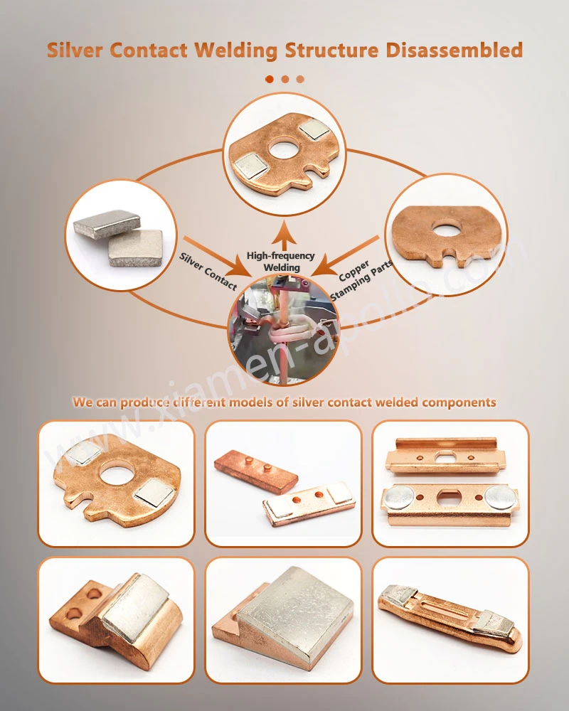
NDT and Shear Testing: ASTM-Based QA Records and Lot Traceability
X-Ray/CT Inspection for Internal Brazing Defects
Visual inspection cannot reliably identify internal voids beneath a silver contact head. For high-current breaker components, X-ray or computed tomography can provide non-destructive evidence of internal joint condition.
The inspection specification should define:
- Inspection area.
- Minimum detectable defect size.
- Maximum permitted void percentage or individual void size.
- Acceptance location.
- Sampling frequency.
- Equipment resolution.
- Lot identification.
- Inspection report format.
Acceptance limits must be agreed with the component drawing or quality plan. A generic "zero void" statement is not technically useful unless the detection threshold is also defined.
Ultrasonic and Metallographic Verification
Ultrasonic inspection can be considered where component geometry and material combination provide sufficient acoustic coupling and signal separation.
For process qualification, destructive metallography remains useful because it directly exposes:
- Braze-layer continuity.
- Filler distribution.
- Interface reaction zones.
- Porosity.
- Cracks.
- Incomplete wetting.
- Localized overheating.
NDT and metallography serve different purposes. NDT supports production screening without destroying the component; metallography provides detailed process-development evidence from selected samples.
Shear Testing and Failure-Mode Analysis
Shear testing should apply a controlled load to the contact head until interface failure or parent-material failure occurs.
The test report should contain the specimen identification, material batch, joint area, maximum force, calculated stress, loading configuration and fracture location.
For example:
Shear stress (MPa) = Maximum shear load (N) ÷ Effective bonded area (mm²)
If the effective bonding area is not measured consistently, shear-strength data from different component geometries cannot be compared directly.
Consult Our Electrical Engineers Today
IATF 16949 Traceability: Material Batch, Brazing Parameters and Final Inspection
AgWC/AgC Material Certification and Batch Records
For automotive-related high-voltage switching components, material traceability should extend from incoming raw material to finished assembly.
A controlled record can include:
- Contact-material grade.
- Silver content or declared composition.
- Tungsten carbide or carbon phase specification.
- Copper grade.
- Filler-metal grade.
- Raw-material supplier.
- Batch number.
- Production date.
- Brazing equipment identification.
- Brazing temperature profile.
- Operator or production-line identification.
- NDT result.
- Dimensional inspection result.
- Mechanical test result.
ISO 9001 and IATF 16949 quality systems can provide the framework for process control and traceability, while the actual component acceptance criteria should remain product-specific.
RoHS and REACH Material Compliance
Material compliance should be documented through controlled declarations and, where required, laboratory testing.
For procurement, the supplier package should distinguish between:
- Material composition declaration.
- RoHS compliance documentation.
- REACH substance-status declaration.
- Incoming material certificate.
- Production-batch traceability.
- Final inspection record.
This separation prevents a compliance document from being incorrectly treated as proof of mechanical or electrical performance.
Process Capability: ±0.01 mm to ±0.05 mm Critical Dimensions
Dimensional capability should be evaluated against the actual engineering drawing. For precision contact assemblies, measurement may involve micrometers, optical systems, CMM equipment, or dedicated gauges.
Where a drawing specifies ±0.01 mm, the supplier should demonstrate process capability using a defined measurement system and sampling method rather than relying on a single inspection result.
For higher-volume production, statistical process control can be applied to dimensions such as contact-head height, support thickness, brazed assembly height, and concentricity.

FAQ: Brazed Silver Contact Assembly Engineering and Purchasing
What determines the required brazing joint strength for a circuit breaker silver contact?
The required value depends on contact geometry, assembly load, thermal cycling, and application duty. Shear strength should be specified in MPa together with the test geometry, bonded area, loading direction, and failure mode.
How is the internal brazing quality of a silver contact assembly verified?
X-ray or CT inspection can identify internal voids and incomplete bonding without destroying the component. Selected samples can then undergo metallographic sectioning and shear testing for process qualification.
What traceability should a supplier provide for AgWC or AgC brazed contacts?
The supplier should link contact-material and copper-support batches to filler-metal records, brazing parameters, NDT results, dimensional inspection, and final lot identification. ISO 9001 or IATF 16949 systems can support this traceability structure.
contact us
For current circuit-breaker programs, send the contact drawing, AgWC/AgC material requirement, and brazing inspection criteria now for your Brazed Silver Contact Assembly, so the manufacturing team can review joint design, tooling, NDT, and production feasibility before your next purchasing release.