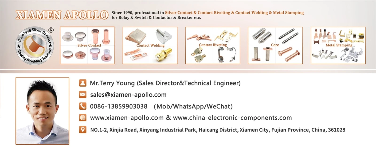
A Monometal Contact Rivet is an electrical contact component made from a single metal throughout its contact head and rivet body. Depending on the switching requirements, the material may be high-purity silver or a silver-based alloy such as AgNi or AgSnO₂. Its electrical conductivity, contact resistance, arc erosion behaviour and resistance to material transfer directly influence switching performance in circuit breakers, contactors and other power distribution equipment.
Material selection is not determined by electrical conductivity alone. Although pure silver provides the highest electrical conductivity among metals, repeated switching operations expose contact surfaces to electrical arcs, localized heating, mechanical impact and material transfer. Silver alloys address some of these operating limitations by modifying the Solid Silver Contacts material's mechanical and thermal behaviour while retaining a substantial proportion of silver's electrical properties.
Understanding the relationship between material composition, rivet construction and switching conditions is essential when specifying Silver Alloy Rivets for industrial power equipment.
What Is a Pure Silver Contact?
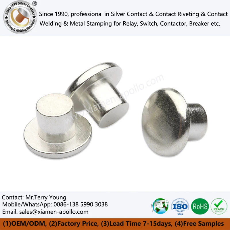
A Silver Solid Contact Rivet is a riveted electrical contact manufactured using one metallic material rather than combining different metals in the contact head and supporting shank.
The entire rivet body has a consistent nominal material composition. Depending on the selected specification, this can include high-purity silver, silver-nickel alloy or silver-tin oxide alloy.
In electrical switching assemblies, the rivet provides a defined contact surface and a mechanical fastening structure. It is installed onto a conductive carrier, moving contact arm or stationary terminal through a riveting operation.
The distinction between monometal and composite contact rivets is particularly important during material selection.
Monometal Contact Construction
A monometal design uses the same material throughout the Silver Alloy Contacts. The contact head and rivet shank therefore share the same nominal alloy composition.
This construction offers several engineering characteristics:
- Consistent material composition throughout the rivet.
- No dissimilar-metal interface between the contact head and rivet body.
- Predictable material behaviour during forming and riveting.
- Simplified material identification and incoming inspection.
- Compatibility with applications requiring a uniform contact material.
For applications where the contact surface and rivet body must use the same electrical contact alloy, this construction provides a direct material configuration.
However, the selected alloy must satisfy both electrical and mechanical requirements. A material suitable for the contact surface is not automatically suitable for every riveting geometry or installation condition.
Monometal vs. Bimetal Contact Rivets
The primary difference between these two constructions is their material configuration.
| Comparison | Monometal Contact Rivet | Bimetal Contact Rivet |
|---|---|---|
| Material structure | Single metallic material | Two different metallic materials |
| Contact head | Same material as rivet body | Usually silver-based material |
| Rivet shank | Same material as contact head | Commonly copper or copper alloy |
| Material interface | No internal dissimilar-metal joint | Requires a bonded interface |
| Material selection | Focuses on one alloy system | Separately considers contact and carrier materials |
| Typical purpose | Uniform material construction | Combines contact properties with conductive support |
Bimetal rivets are commonly selected when a silver-based contact surface is required together with a copper-based supporting structure.
Monometal designs, by comparison, are appropriate when a single material composition can satisfy the electrical, thermal and mechanical requirements of the assembly.
Neither construction is universally preferable. The decision depends on contact current, switching frequency, temperature rise, contact force, manufacturing requirements and material cost.
Electrical Conductivity of High-Purity Silver Contacts
Silver has the highest electrical conductivity of all metals under standard reference conditions. Its conductivity makes it particularly suitable for Silver Contact Points applications where minimizing resistive losses is important.
In a switching device, electrical current passes through the contact interface when the movable and stationary contacts are closed.
The resulting resistance depends on several factors:
- Bulk electrical resistivity of the contact material.
- Actual microscopic contact area.
- Contact force and surface deformation.
- Surface films and contamination.
- Temperature at the contact interface.
- Mechanical stability during repeated switching.
Contact Resistance and Temperature Rise
Contact resistance is not determined solely by the bulk conductivity of silver.
Even when two contact surfaces appear flat, actual electrical conduction occurs through microscopic contact spots known as asperities. These Silver electrical contacts spots carry the current across the interface.
The real contact area is generally much smaller than the apparent contact area.
Contact force causes local deformation of these microscopic surface features, increasing the effective conductive area and reducing constriction resistance.
If the contact force is insufficient, electrical resistance may increase. This can produce localized heating during continuous current transmission.
The resulting temperature rise may accelerate surface oxidation, material degradation and mechanical changes in the contact assembly.
Consequently, electrical testing should evaluate the complete contact assembly rather than relying exclusively on the conductivity specification of the raw silver material.
Why High-Purity Silver Is Not Always the Best Switching Material
High-purity silver offers excellent conductivity, but its relatively low resistance to arc-induced material degradation limits its suitability in certain switching environments.
When electrical contacts separate under load, the electric field can ionize the surrounding medium and establish an arc between the separating surfaces.
The arc generates concentrated thermal energy. Depending on the switching current, circuit voltage, opening speed and arc-control structure, the Solid contacts surface may experience localized melting and material loss.
Pure silver can exhibit:
- Localized melting under arc exposure.
- Material transfer between opposing contacts.
- Contact welding under unfavourable switching conditions.
- Surface deformation after repeated switching.
- Erosion that changes the contact geometry.
These effects are particularly relevant to devices operating under frequent electrical switching conditions.
Therefore, material selection must consider the complete switching duty rather than conductivity alone.
Download Contact Material Spec Sheet
Silver Alloy Materials Used in electrical spring contacts
Silver alloy materials are developed to improve the switching characteristics of electrical contacts.
By introducing selected alloying elements or dispersed compounds, manufacturers can modify hardness, arc erosion resistance, welding behaviour and thermal stability.
Two commonly used material systems are silver-nickel and silver-tin oxide.
Silver Nickel (AgNi)
Silver-nickel is a solid electrical contacts alloy consisting of a silver matrix with nickel as the alloying component.
Nickel increases the mechanical hardness of the material compared with high-purity silver and can improve resistance to contact deformation and material transfer.
Its electrical conductivity is lower than that of pure silver, but the material provides a useful balance between conductivity and switching behaviour.
Typical engineering characteristics include:
- Higher hardness than high-purity silver.
- Improved resistance to mechanical deformation.
- Reduced tendency toward contact welding in suitable applications.
- Good electrical conductivity relative to many other contact materials.
- Suitability for repeated switching operations.
- AgNi is used in various relay, switch and low-voltage electrical contact systems.
Its suitability depends on the nickel content, material processing, contact geometry and actual switching conditions.
Silver Tin Oxide (AgSnO₂)
Silver-tin oxide is a composite electrical contact material consisting of a silver matrix containing dispersed tin oxide particles.
Unlike conventional metallic solid-solution alloys, AgSnO₂ relies on the distribution of an oxide phase within the silver matrix to modify its switching behaviour.
The tin oxide phase contributes to resistance against arc-induced erosion and contact welding.
Important characteristics include:
- Improved resistance to electrical arc erosion.
- Reduced tendency toward contact welding.
- Good thermal stability under switching loads.
- Suitable performance in applications involving repeated switching.
- Electrical conductivity lower than that of pure silver.
AgSnO₂ is widely considered for contact applications in relays, contactors and circuit protection devices.
Its performance depends on the oxide distribution, material density, manufacturing process and contact operating conditions.
Comparison of Silver, AgNi and AgSnO₂
The following table summarizes their general engineering characteristics.
| Property | High-Purity Silver | AgNi | AgSnO₂ |
|---|---|---|---|
| Main composition | High-purity Ag | Silver and nickel | Silver and tin oxide |
| Electrical conductivity | Highest among the three | Lower than pure silver | Lower than pure silver |
| Mechanical hardness | Relatively low | Higher than pure silver | Depends on composition and processing |
| Arc erosion resistance | Limited in demanding switching conditions | Improved for suitable duties | Generally suitable for demanding switching duties |
| Welding resistance | Relatively limited | Improved | Improved |
| Typical application focus | Low-resistance conduction | General switching contacts | Arc-intensive switching contacts |
These materials should not be treated as interchangeable.
A material with higher conductivity may not provide the required resistance to welding or arc erosion. Conversely, a material with improved arc resistance may introduce additional electrical resistance and temperature rise.
The correct specification must reflect the electrical duty cycle and the mechanical requirements of the complete switching mechanism.

Arc Erosion and Contact Welding Mechanisms
Arc erosion and contact welding are two major failure mechanisms affecting Solid Ag Contacts.
Both are associated with the thermal and electrical conditions generated during switching operations.
Arc Formation During Contact Separation
When contacts separate while carrying current, the effective contact area decreases.
Current density increases at the remaining conductive points, producing localized heating.
Under suitable electrical conditions, the voltage across the separating gap becomes sufficient to sustain an electrical discharge.
The resulting arc produces intense localized heating and may cause:
- Melting of the contact surface.
- Evaporation of contact material.
- Material ejection and transfer.
- Formation of craters and surface irregularities.
- Changes in contact resistance and geometry.
- Repeated exposure gradually alters the contact surface.
If erosion becomes excessive, the contact may no longer maintain the required electrical or mechanical performance.
Contact Welding During Closing Operations
Contact welding occurs when opposing contact surfaces become metallurgically bonded.
Several factors can contribute to this condition:
- Excessive localized temperature.
- High electrical current.
- Contact bounce during closing.
- Surface contamination.
- Material transfer between opposing contacts.
- Insufficient contact separation force.
When the contact surfaces partially melt, local material bridges may form.
After cooling, these bridges can solidify and mechanically connect the opposing contacts.
The switching mechanism must then generate sufficient opening force to separate them. If the bonding force exceeds the available mechanical force, the contacts may remain stuck.
Silver alloy materials can reduce the tendency toward this failure, but the result depends on the electrical and mechanical design of the switching system.
How Silver Alloys Modify Arc Behaviour
The addition of nickel or tin oxide changes the physical structure of the contact material.
In AgNi, the nickel-containing structure modifies the mechanical properties and influences the behaviour of the Solid Rivet Contacts surface during thermal loading.
In AgSnO₂, the dispersed oxide phase contributes to resistance against material loss and welding under electrical arc exposure.
However, alloy composition alone cannot determine service life.
Arc duration, current magnitude, voltage, switching frequency, contact pressure and arc-extinguishing design must all be considered.
Consult Our Electrical Engineers Today
Manufacturing Considerations for Monometal Contact Rivets
The performance of a Silver Contact Point depends on both material characteristics and manufacturing consistency.
A suitable raw material can still produce an unstable contact assembly if dimensional accuracy, surface condition or riveting deformation is poorly controlled.
Raw Material Composition
Material identification is the first stage of quality control.
For high-purity silver and silver alloys, incoming inspection should verify the specified material grade and chemical composition.
Relevant inspection methods may include:
- Chemical composition analysis.
- Electrical conductivity measurement.
- Hardness testing.
- Density measurement where applicable.
- Metallographic examination.
For AgSnO₂ materials, oxide distribution and material uniformity are also important considerations.
For AgNi, nickel distribution and the resulting material properties should be controlled according to the specified grade.
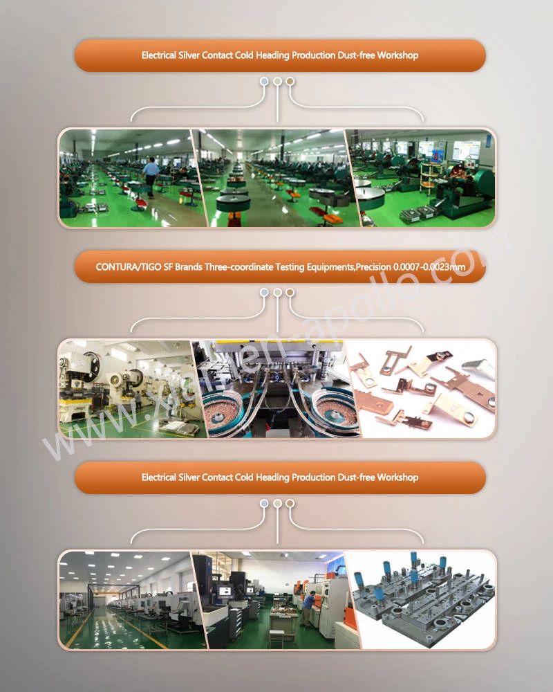
Cold Heading and Rivet Forming
Cold heading is a common manufacturing process for forming metal rivets.
The process uses compressive force to transform wire or rod material into a rivet geometry without bulk melting.
Depending on the material and geometry, manufacturing operations may include:
- Wire or rod material preparation.
- Cutting to a defined blank length.
- Head forming.
- Shank sizing.
- Dimensional inspection.
- Surface cleaning and finishing.
For silver-based contact materials, forming parameters must account for material ductility, work hardening and the required head geometry.
Excessive deformation may cause dimensional variation or surface defects.
Insufficient forming pressure may result in incomplete head formation or inconsistent dimensions.
Dimensional Accuracy and Contact Geometry
Contact geometry influences the mechanical and electrical behaviour of the assembled contact.
Important dimensions include:
| Inspection Item | Engineering Significance |
|---|---|
| Head diameter | Determines the nominal contact surface area |
| Head thickness | Influences material volume and contact profile |
| Shank diameter | Determines compatibility with the mounting hole |
| Rivet length | Affects installation and fastening conditions |
| Concentricity | Influences alignment during assembly |
| Surface flatness | Affects initial contact engagement |
| Surface condition | Influences contact interface stability |
Actual dimensional tolerances must be established according to the component drawing and assembly requirements.
A universal tolerance should not be assigned to all rivet geometries because material ductility, forming sequence and component dimensions vary.
Riveting and Assembly Quality
The riveting process creates a mechanical connection between the Pure Silver Contact and its supporting component.
Insufficient riveting deformation may cause loose installation, while excessive deformation can damage the contact head or distort the supporting carrier.
Inspection should consider:
- Rivet retention strength.
- Head deformation.
- Shank expansion.
- Contact alignment.
- Cracking or visible material damage.
- Mechanical stability after assembly.
For electrical applications, the assembled component should also undergo electrical resistance testing where required by the product specification.
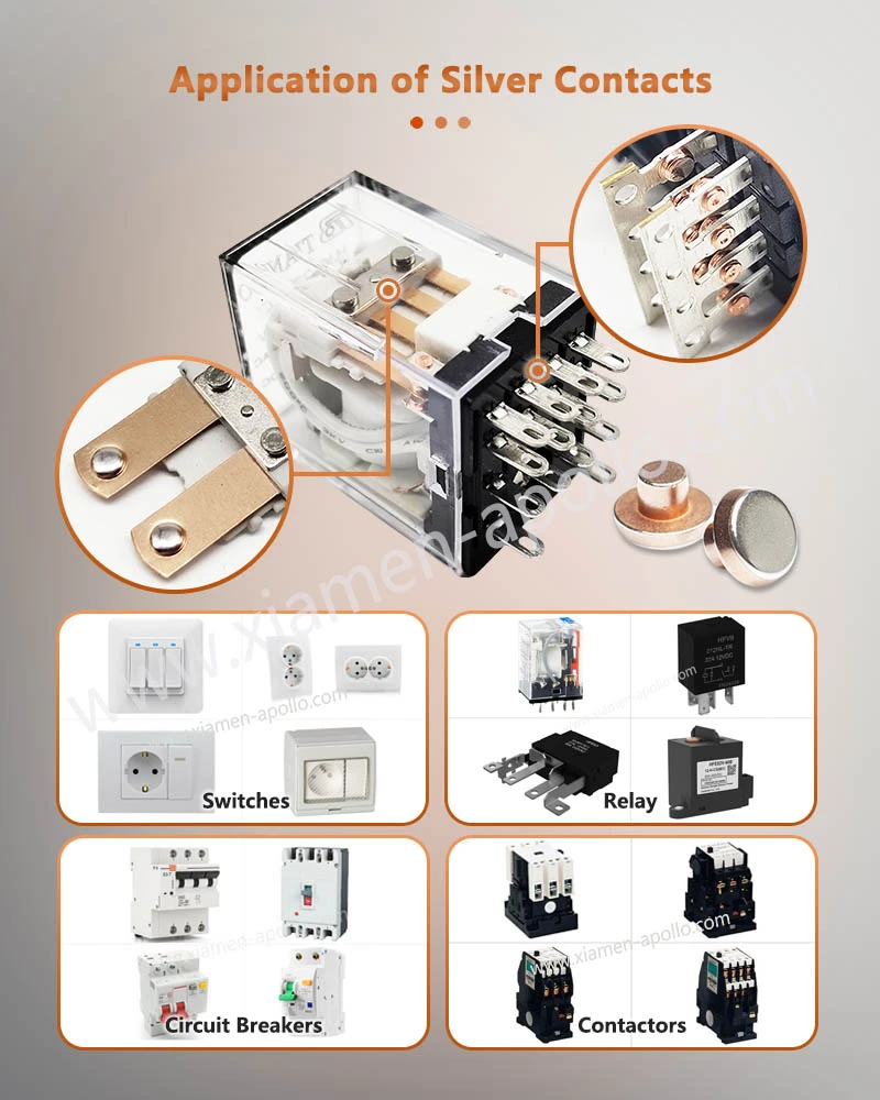
Applications in Circuit Breakers, Contactors and Relays
Different switching devices impose different requirements on their contact materials.
The selection of a Solid Silver Contact Rivet should therefore be based on the electrical function and operating conditions of the equipment.
Circuit Breakers
Circuit breakers use electrical contacts to establish and interrupt current paths.
During normal operation, the contacts must carry the rated current without excessive temperature rise.
During fault interruption, the contact system may be exposed to significantly higher electrical and thermal stresses.
Material selection must consider:
- Rated operational current.
- Short-circuit interruption capability.
- Contact opening speed.
- Arc chamber design.
- Contact pressure.
- Expected electrical endurance.
Silver-based contact materials are used in different low-voltage switching configurations, with the specific grade selected according to the device design.
AC and DC Contactors
Contactors operate through repeated electromagnetic switching.
Their contact systems experience electrical loading during both closing and opening operations.
AC and DC switching duties should not be treated as equivalent.
In AC circuits, current naturally passes through zero during each cycle, providing opportunities for arc extinction.
In DC circuits, there is no natural periodic current zero. Arc interruption therefore depends more heavily on the contact separation distance, magnetic blowout system and arc-extinguishing structure.
For this reason, DC contact applications require particular attention to arc erosion and contact welding.
AgNi and AgSnO₂ may be evaluated depending on the rated voltage, current and switching duty.
Industrial Relays
Relays use movable and stationary contacts to control electrical circuits.
The contact material must maintain stable electrical conduction while accommodating repeated mechanical movement.
Relevant selection parameters include:
- Switching current.
- Switching voltage.
- Electrical load characteristics.
- Contact force.
- Switching frequency.
- Expected operating cycles.
Silver-based materials are used in industrial relays because of their electrical conductivity and adaptability to different contact configurations.
For low-level signal switching, surface contamination and contact film formation may be as important as bulk conductivity.
Power Distribution and Electrical Control Equipment
Electrical distribution assemblies use various contact structures to connect, disconnect and control current paths.
Depending on the design, silver contact rivets may be installed in:
- Low-voltage switching assemblies.
- Industrial control equipment.
- Electromagnetic contactors.
- Protective switching devices.
- Electrical control relays.
The material grade should be selected according to the actual electrical duty rather than the equipment category alone.
Conclusion: Material Composition Determines Contact Performance
A Solid Silver Contact Rivet provides a single-material construction in which the contact head and rivet body share the same nominal metallic composition.
High-purity silver offers the highest electrical conductivity, making it suitable for applications where minimizing contact resistance is a primary requirement. However, repeated switching under electrical load can expose pure silver to arc erosion, localized melting and contact welding.
AgNi and AgSnO₂ provide alternative material systems with modified mechanical and switching characteristics. AgNi is considered where conductivity and mechanical resistance must be balanced, while AgSnO₂ is frequently evaluated for applications involving more demanding arc exposure.
The final material specification must account for electrical loading, contact geometry, switching frequency, mechanical force and manufacturing conditions. Conductivity alone cannot determine the service performance of a complete switching contact assembly.
For engineering and procurement teams, the most effective selection process combines material verification, dimensional control, mechanical inspection and electrical endurance testing.
contact us
For upcoming circuit breaker, contactor and relay production programs, submit your Monometal Contact Rivet drawings, material grades and annual volume requirements for a technical manufacturing review. Confirm the forming process, dimensional tolerances, material availability and inspection criteria before finalizing the production schedule.