

In relay manufacturing, brazed silver contacts are the core components determining switching performance and service life, while the welding process is a key control link ensuring the stable functioning of button contact bimetal overlays. Whether it's a traditional electromagnetic relay or a high-reliability industrial control relay, the connection quality between the electrical contact welding and the conductor and armature directly affects electrical performance, mechanical life, and environmental adaptability. For all types of welding components, establishing systematic and quantifiable welding process standards is fundamental to ensuring product consistency.
Core Objectives of Contact Welding Process Standards
Relays must withstand high-frequency operation and load impacts during actual operation. The welded joints not only conduct current but also withstand periodic mechanical stress. Therefore, Electrical Contact Kits must meet three basic objectives:
First, low contact resistance. The resistance of the welded area should be significantly lower than the resistance of the contact material itself, with a typical target of ≤5mΩ. If there are incomplete welds or oxide inclusions in the welded area, it will lead to localized heating, which can induce material softening or weld failure.
Second, high mechanical strength. The weld joints must pass tensile and shear tests, typically with a tensile strength standard ≥15N (adjusted according to model). For fixed and moving contact structures, the moving contact experiences frequent impacts; insufficient weld strength can easily lead to detachment or displacement.
Third, long-term chemical stability. The welded area must remain stable in high-temperature, high-humidity, and salt spray environments, without rapid oxidation or corrosion. Especially in Silver Cadmium Oxide Contacts and AgCdO Contacts applications, the quality of the weld interface directly affects arc resistance.

Welding Process Parameter Control
Silver Tin Oxide Contacts primarily employ resistance spot welding or laser welding techniques. Taking resistance spot welding as an example, the core control parameters include welding current, energizing time, and electrode pressure.
1. Current and Time Control
The welding current determines the heat input intensity, while time determines heat accumulation. Parameter settings should ensure the formation of a stable weld nugget without overheating. For Welding Button Contact structures, excessive current can easily lead to contact edge collapse; insufficient current results in a weak weld.
2. Electrode Head Maintenance
The electrode head is typically made of chromium zirconium copper, and its end face shape directly affects the current distribution. Standards require the end face diameter to match the dimensions of AgSnO2 Based Contacts, with flatness controlled within 0.01mm, and regular grinding is necessary. Electrode wear can lead to abnormal current density, thus affecting the quality of Silver Contact Welding.
3. Pressure Control
Insufficient pressure will result in excessively high contact resistance, while excessive pressure may cause deformation. For Brazed Composite Rivet Electrical Contacts or Brazed Contact on Terminal structures, pressure control is particularly critical to prevent composite layer separation.

Post-Welding Quality Inspection and Verification
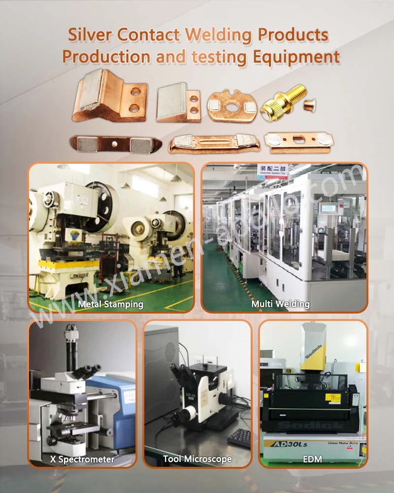
Post-welding quality control is a crucial part of closed-loop management and should combine electrical testing, mechanical testing, and metallographic analysis.
1. Contact Resistance Testing
Use a micro-ohmmeter for random sampling to confirm that the resistance of the welded area meets design standards. If abnormal fluctuations are found in the batch data for Resistance Welding Contacts, the parameters should be immediately rechecked.
2. Tensile and Shear Testing
Verify whether the weld strength meets design requirements. For Contact Assembly Welding structures, insufficient strength is usually related to uneven heat input or interface contamination.
3. Metallographic and Cross-Sectional Analysis
Observe the weld nugget diameter and fusion depth through cross-sections to confirm complete metallurgical bonding. For Silver Brazing Products and Silver Brazing Contacts, special attention should be paid to checking the interface wetting condition.
Frequently Asked Questions
1. What is the primary function of Butt welding Silver Contact?
It connects conductive components to the movable contact structure, directly influencing electrical conductivity, mechanical lifespan, and reliability.
2. What are the common causes of defective welding for BAg-series silver brazing alloy?
Common causes include improper current or pressure, electrode wear, and interface contamination or residual oxides.
3. What is the standard acceptance criterion for contact resistance for Buttons Contacts?
Generally, the contact resistance in the welded area is required to be ≤5 mΩ, though specific limits are adjusted based on product design standards.
contact us
For support regarding relay contact soldering standards or Silver Bonded Contact Components application solutions, please contact us.
