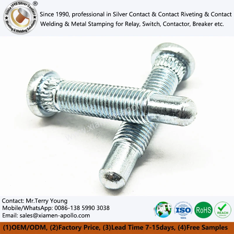
Self-clinching screws secure threaded fasteners in sheet metal by forcing the panel material to flow into an annular locking feature under controlled compressive force. The resulting mechanical interlock resists rotation and push-out without welding or tapping when the panel material, hole geometry, fastener design, and installation conditions are compatible. If a self-clinching screw rotates or pulls out, increasing press force or selecting a larger fastener is not a valid corrective action until the failure mechanism has been identified.
Self-Clinching Screw Selection: Verify Panel Properties Before Ordering
Panel Hardness and Thickness Determine Clinching Feasibility
Self-clinching fasteners depend on local plastic deformation of the host sheet. During installation, the panel material flows into the fastener's locking groove or undercut, creating resistance to rotation and axial displacement.
The panel must be sufficiently ductile and generally softer than the fastener's effective locking features. A sheet that is too hard may resist material flow, while a sheet that is too thin may not provide enough material to fill the locking geometry.
Before specifying a Self-Clinching Screw, verify:
- Panel material: Identify the exact alloy and grade, such as low-carbon steel, stainless steel, or aluminum.
- Sheet thickness: Confirm the actual minimum and maximum thickness against the fastener manufacturer's approved range.
- Hardness: Check the panel's measured hardness rather than assuming that identical thickness means identical installation behavior.
- Ductility: Evaluate whether the sheet can deform locally without cracking or excessive thinning.
- Surface coating: Identify zinc plating, paint, powder coating, or other treatments that may affect seating or dimensional compatibility.
- Edge distance: Confirm the distance from the installation hole to the panel edge and adjacent features against the manufacturer's specification.
A fastener suitable for a ductile carbon-steel panel may not perform equivalently in a harder stainless-steel sheet of the same nominal thickness.
Hole Diameter, Tolerance, and Burr Direction Control Material Flow
The installation hole is a functional dimension, not simply a clearance opening. If the hole is oversized, the panel may not fill the locking groove sufficiently. If it is undersized, insertion force can rise, the panel may distort, or the fastener may not seat correctly.
| Inspection item | Failure mechanism | Required control |
|---|---|---|
| Hole diameter | Oversized holes reduce locking engagement; undersized holes can cause distortion | Follow the specified fastener installation drawing |
| Hole roundness | Uneven engagement can reduce anti-rotation resistance | Inspect hole geometry where required |
| Burr height and direction | Burrs can prevent flush seating or create local stress concentrations | Define deburring and punching direction |
| Panel thickness | Insufficient material can weaken retention | Verify the approved thickness range |
| Hole-to-edge distance | Edge cracking or panel breakout can reduce retention | Follow the manufacturer's minimum edge-distance requirement |
| Coating condition | Coating buildup or damage can affect seating and corrosion protection | Define the coating sequence and acceptance criteria |
Do not apply a universal hole tolerance across different fastener sizes, panel alloys, or thicknesses. The required diameter and tolerance must come from the selected fastener's installation specification and be confirmed through representative trials.
Self-Clinching Screw Installation: Control Press Alignment and Force
The Locking Mechanism Depends on Plastic Flow, Not Friction Alone
During proper installation, a press applies axial force to seat the fastener while the supporting anvil holds the panel. The panel material flows into the locking feature and forms a mechanical interlock.
Retention depends on the resulting geometry and material engagement. Press force is a process input, not proof of a successful joint. Excessive force cannot reliably compensate for an oversized hole, incompatible panel hardness, insufficient sheet thickness, or a poorly designed fastener.
The installation process should establish and maintain:
- Correct punch or pressing-head geometry.
- A flat, stable supporting anvil.
- Parallelism between the pressing head and supporting surface.
- Concentric alignment between the fastener and installation hole.
- The specified installation direction.
- A controlled press-force or displacement window validated for the selected assembly.
Press-Head Alignment and Anvil Support Prevent Local Damage
An angled press head or uneven support can create nonuniform deformation around the fastener. One side may seat first while the opposite side remains insufficiently engaged. The visible head may appear acceptable even though the locking feature has not formed correctly.
Inspect the tooling setup for:
- Head-to-anvil parallelism.
- Concentricity between the ram, fastener, and hole.
- Anvil flatness and adequate support around the installation point.
- Correct fastener orientation and feeding.
- Panel movement during the pressing cycle.
- Signs of local buckling, cracking, or permanent panel distortion.
Installation tooling should be qualified for the actual panel and fastener combination. A tooling setup that works for one material grade should not automatically be transferred to another grade or coating condition.
Establish a Validated Force Window Instead of Increasing Pressure
No single press-force value applies to every Self-Clinching Screw. The required force varies with fastener geometry, panel alloy, thickness, hardness, hole diameter, and equipment configuration.
Establish the process window through controlled trials using approved fastener and panel specifications. Record the force-displacement response when suitable monitoring equipment is available, and verify the finished joint using the required retention tests.
| Process variable | Potential defect | Verification method |
|---|---|---|
| Press force | Incomplete seating or panel deformation | Force monitoring and dimensional inspection |
| Press alignment | Uneven engagement and tilted installation | Visual inspection and installed-height measurement |
| Hole diameter | Insufficient locking or excessive insertion resistance | Calibrated hole measurement |
| Panel hardness | Incomplete material flow or cracking | Material verification and trial installation |
| Support condition | Local bending or inconsistent seating | Tooling inspection and first-piece validation |
| Fastener orientation | Damaged threads or incorrect seating | Visual inspection and thread gauging |
The acceptable process limits must be established from the fastener specification and verified on production-representative parts. Do not invent a nominal force or tolerance where the design documentation does not provide one.
Download Contact Material Spec Sheet
Self-Clinching Screw Failure Analysis: Rotation, Push-Out, and Panel Damage
A Rotating Fastener Indicates Insufficient Anti-Rotation Engagement
A fastener that rotates during screw tightening may have insufficient engagement between the panel and the locking feature. Increasing installation pressure without identifying the cause can deform the panel while leaving the underlying problem unresolved.
Check the following in sequence:
- Hole enlargement: Measure the actual hole diameter and compare it with the approved drawing.
- Insufficient material flow: Inspect a representative cross-section to determine whether the panel material fills the locking groove.
- Panel hardness: Confirm the actual material grade and hardness against the approved specification.
- Fastener geometry: Verify the part number, locking feature, and dimensional revision.
- Installation alignment: Inspect the press head, anvil, and installed fastener for eccentricity.
- Threading torque: Confirm that the assembly torque is within the approved limit and that the observed rotation is not caused by an unrelated assembly issue.
Where feasible, examine a failed joint in cross-section. The extent and symmetry of panel engagement provide more useful evidence than the head appearance alone.
Push-Out Failure Requires Examination of Both the Fastener and the Panel
A fastener that pulls out under axial loading may indicate inadequate locking engagement, local panel failure, or damage introduced during installation.
Inspect for:
- Panel tearing around the installation hole.
- Insufficient sheet thickness or material strength.
- Incomplete engagement of the locking groove.
- Cracks or permanent deformation caused by excessive force.
- Incorrect edge distance.
- Fastener or panel dimensional variation.
Distinguish between fastener displacement and panel failure. If the panel material tears away around the fastener, simply increasing the fastener size may not solve the problem. The panel design, edge distance, material properties, or load distribution may require revision.
Flush Seating Is a Dimensional Check, Not a Retention Test
A fastener head that sits flush with the panel can still have inadequate anti-rotation or push-out resistance. Visual inspection confirms seating geometry, but it cannot establish the strength of the mechanical interlock.
Use separate acceptance criteria for:
- Installed height or flushness.
- Fastener perpendicularity.
- Panel distortion and cracking.
- Thread condition and gauge acceptance.
- Anti-rotation resistance.
- Axial push-out resistance.
Define the required test load, fixture arrangement, loading direction, and acceptance limit in the drawing, engineering specification, or approved validation plan. Record the actual result and correlate it with the applicable product and process revisions.
Anti-Rotation and Push-Out Tests Must Reflect Actual Service Loads
Anti-rotation testing evaluates torque resistance applied to the installed fastener. Push-out testing evaluates resistance to axial displacement under a defined loading condition. The two tests assess different failure modes and should not be treated as substitutes for each other.
Use representative panel material, thickness, hole preparation, coating condition, and installation equipment during validation. A test coupon made from a different material or manufactured with a different hole process may not represent production performance.
Self-Clinching Screw Troubleshooting: Correct the Root Cause Before Changing the Design
Why Increasing Press Force Is Not the Default Corrective Action
When a fastener rotates, first determine whether the panel material has formed the required mechanical interlock. Excessive press force can enlarge the damaged area, deform the sheet, distort adjacent features, or compromise the fastener's installed geometry.
A controlled corrective-action sequence is:
- Quarantine affected production and identify the relevant lot.
- Verify the fastener part number and panel material specification.
- Measure the installation hole and panel thickness.
- Inspect press alignment and support conditions.
- Examine representative failed joints.
- Conduct controlled trials with one variable changed at a time.
- Repeat anti-rotation, push-out, and dimensional checks before release.
- Any adjustment must be documented and validated before production resumes.
Equal Panel Thickness Does Not Mean Equivalent Fastener Performance
Two panels with identical nominal thickness can behave differently during installation because their hardness, yield strength, ductility, grain structure, and coating conditions may differ.
For example, a low-carbon steel sheet and a stainless-steel sheet of equal thickness may not provide equivalent material flow around the same locking feature. Aluminum panels also require specific compatibility checks because their deformation and local bearing behavior differ from those of steel.
Fastener selection must therefore use the complete panel specification, not thickness alone. If the panel alloy or temper changes, confirm whether the existing fastener designation and installation process remain approved.
Welding a Failed Self-Clinching Joint Requires Engineering Approval
Welding a self-clinching fastener as a repair is not a routine substitute for correct installation. Welding may affect panel properties, zinc coating, corrosion resistance, dimensional accuracy, and nearby components. It can also introduce heat-affected zones, distortion, or additional finishing requirements.
Any welding-based repair should be treated as a special engineering deviation. The design authority must approve the repair method, joint strength requirements, inspection criteria, corrosion protection, and applicable qualification tests before implementation.
Where the assembly is safety-related or subject to a regulated product specification, assess whether the repair affects the original qualification or certification basis.
Consult Our Electrical Engineers Today
Self-Clinching Screw Production Control: First-Article Validation and Change Management
First-Article Inspection Must Confirm the Complete Installed Joint
Before mass production, perform a first-article installation using the intended production fastener, panel material, hole-making process, tooling, and press settings.
The inspection plan should include:
- Fastener identity, thread dimensions, and locking geometry.
- Panel material grade, thickness, and hardness where specified.
- Installation-hole diameter and condition.
- Installed height, perpendicularity, and panel distortion.
- Thread gauge results.
- Anti-rotation and push-out test results against approved limits.
- Surface-coating condition before and after installation.
Record the tooling configuration and process settings used to produce the validated sample. First-article approval should be based on measurable acceptance criteria rather than visual appearance alone.
Lock the Approved Process and Revalidate Relevant Changes
Once the assembly passes validation, document the approved process parameters and inspection methods. Define the limits within which routine production may operate and specify the conditions that trigger requalification.
Reassessment is required when a change could affect material flow, locking geometry, or joint retention. Examples include:
- A change in panel alloy, temper, hardness, or thickness.
- A change in fastener supplier, material, coating, or geometry.
- A revised hole diameter, punching tool, or deburring method.
- A change in pressing equipment, head, anvil, or alignment.
- A change in installation force or displacement settings.
- A change in the specified assembly torque or service loading.
Use risk-based change control to determine the scope of revalidation. A change to a nonfunctional packaging feature may require different checks from a change to the panel material or locking geometry.
Lot Traceability and Quality Documentation Support Supplier Qualification
Purchasing and quality teams should define the documentation required for each fastener program. Depending on the application, this may include material certificates, dimensional inspection reports, coating records, mechanical test results, lot identification, and approved process revisions.
ISO 9001 and IATF 16949 requirements should be referenced only where applicable to the supplier's certified scope and the customer's contractual requirements. RoHS and REACH documentation addresses applicable substance restrictions and chemical compliance; it does not establish mechanical retention strength.
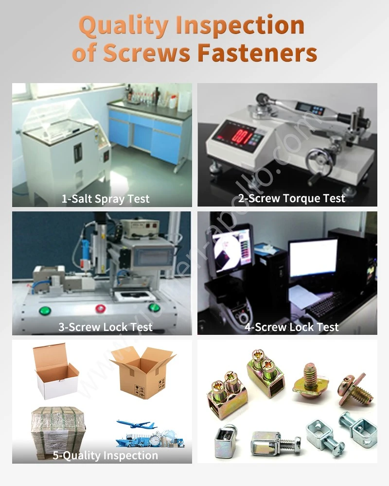
Likewise, salt-spray testing under ASTM B117 can assess corrosion behavior under specified test conditions, but it does not directly prove anti-rotation or push-out performance. Select each test according to the failure mode or compliance requirement being evaluated.
A controlled inspection plan should link each acceptance requirement to its measurement method, sample frequency, record, and disposition rule. This gives purchasing, engineering, and QA teams a common basis for supplier approval and ongoing production monitoring.
FAQ: Self-Clinching Screw Purchasing and Engineering
1. Why does a self-clinching screw rotate after installation?
Common causes include an oversized hole, insufficient panel material flow, incompatible panel hardness, incorrect fastener geometry, or press misalignment. Measure the hole and inspect the locking engagement before changing installation force or fastener size.
2. How do you verify the retention strength of a self-clinching screw?
Use separate anti-rotation torque and axial push-out tests with defined fixtures, loading conditions, and acceptance limits. Confirm installed height, thread condition, and panel integrity as additional checks. The test requirements should follow the approved drawing or engineering validation plan.
3. What information is required to obtain a quotation for custom self-clinching screws from a China factory?
Provide the fastener drawing, thread specification, panel material and thickness, hole dimensions, surface finish, annual demand, order quantity, and required inspection criteria. Include anti-rotation and push-out requirements if specified, so the supplier can assess compatibility and quotation scope.
contact us
Request an engineering review now for your Self-Clinching Screw project: submit the panel drawing, fastener specification, and retention requirements to establish a validated installation process before committing to production tooling.