Solid pure silver (FASg) and silver-nickel (AgNi10) have different electrical and mechanical characteristics when used in Silver Contacts for MCBs. FASg provides higher electrical conductivity and low initial contact resistance, making it suitable for signal circuits operating below 1 A. AgNi10 offers greater hardness and resistance to mechanical wear, but its lower conductivity can increase the difficulty of maintaining stable contact resistance under low contact pressure. Material selection should therefore consider the relay's actual contact force, switching current, surface condition, and required operating life.

Low-Load Switching Challenges in Micro Relays: Below 1 A
Micro relays used in smart home controllers, communication equipment, electronic control modules and signal switching circuits frequently operate at currents below 1 A. Under these conditions, contact material selection directly affects electrical continuity, signal transmission and long-term contact resistance stability.
Unlike power relays switching several amperes, low-load micro relays may not generate sufficient electrical or thermal energy to disrupt surface contamination films during contact closure. Consequently, a contact pair with acceptable bulk conductivity can still exhibit unstable electrical performance if its surface condition or contact pressure is unsuitable.
Surface Film and Contact Resistance at Low Switching Currents
Silver has the highest electrical conductivity among common engineering metals, approximately 105% IACS at 20°C for high-purity material under standard reference conditions.
Its surface behavior also makes it suitable for low-current electrical contacts. Silver oxide is relatively conductive compared with many other metal oxides. However, silver can react with sulfur-containing compounds in the surrounding environment and form silver sulfide (Ag2S), which may increase contact resistance.
At currents below 1 A, the electrical energy available during switching is often insufficient to break down surface films through localized heating or electrical discharge.
The resulting contact resistance depends on several interacting factors:
- Silver purity: FASg with Ag content typically ≥99.95%, subject to the specified material grade.
- Surface contamination: Sulfur compounds, organic residues and plating contaminants.
- Contact force: Actual force at the closed contact position, measured in N.
- Surface geometry: Contact diameter, flatness and surface roughness.
- Environmental conditions: Temperature, relative humidity and corrosive gas concentration.
Contact Force and Real Contact Area
Two apparently flat silver contact surfaces do not establish electrical contact across their entire nominal area. Current passes through microscopic contact spots formed by surface asperities.
Increasing contact force generally increases the real contact area and reduces constriction resistance. However, excessive force increases the mechanical load on the relay armature, spring and electromagnetic drive system.
For micro relays, the contact force must be evaluated together with the return spring force, electromagnetic operating force and required release characteristics.
The following parameters should be measured during relay development:
| Engineering Parameter | Evaluation Requirement | Effect on Low-Load Switching |
|---|---|---|
| Closed contact force | Measured in N | Determines real contact area |
| Initial contact resistance | Measured in mΩ | Determines initial voltage drop |
| Contact surface roughness | Ra in μm | Affects microscopic contact points |
| Contact diameter | Specified in mm | Influences nominal contact area |
| Contact resistance variation | Measured over switching cycles | Indicates electrical stability |
Electrical Contact Material Selection for Signal Circuits
For micro relay circuits below 1 A, low contact resistance and surface condition are often more important than resistance to severe arc erosion.
FASg is generally suitable when the primary requirement is low electrical resistance under relatively low mechanical loading.
AgNi10 becomes more attractive when repeated mechanical contact, contact deformation and wear resistance are more significant concerns.
The final choice should be verified using the actual relay's rated voltage, switching load, contact force and environmental test conditions.
Download Contact Material Spec Sheet
Solid Pure Silver (FASg): Conductivity and Low-Load Contact Performance
Solid pure silver electrical contacts are commonly considered for micro relays requiring low electrical resistance and stable signal conduction. Their main advantage is the combination of high bulk conductivity, relatively low material hardness and favorable electrical contact behavior under suitable surface and force conditions.
Electrical Conductivity of FASg: Approximately 105% IACS
High-purity silver has a reference electrical conductivity of approximately 105% IACS at 20°C. The actual value depends on purity, material processing, temperature and measurement conditions.
Compared with AgNi10, pure silver provides a lower bulk electrical resistance.
For low-load switching, this characteristic helps reduce voltage drop and resistive heating at the contact interface.
However, bulk conductivity alone cannot determine the final contact resistance. Surface contamination, contact pressure and microscopic contact geometry remain important variables.
Surface Oxide Behavior and Contact Resistance
Silver oxide has substantially different electrical behavior from the insulating oxide films formed on metals such as copper and nickel.
This characteristic is beneficial for low-current contacts because silver surfaces can maintain electrical conduction without relying on high switching energy to remove a strongly insulating oxide layer.
Nevertheless, pure silver is not immune to environmental contamination. Silver sulfide formation can affect contact resistance, particularly in environments containing sulfur-bearing gases.
For relay applications, material selection should therefore be accompanied by surface cleanliness control, appropriate storage conditions and environmental testing.
Mechanical Limitations of Solid Silver Contacts
The relatively low hardness of pure silver makes it easier to deform under concentrated contact pressure.
Repeated switching can produce:
- Localized plastic deformation at the contact interface.
- Contact surface flattening and material displacement.
- Mechanical wear under repeated opening and closing.
- Changes in contact geometry and contact force distribution.
These effects become more significant when the relay has high operating frequency, excessive contact force or an unsuitable contact surface geometry.
Pure silver is therefore not automatically the best option for every micro relay. Its electrical advantages must be balanced against the mechanical requirements of the contact assembly.
Manufacturing Considerations for Solid Silver Contacts
Solid silver contacts can be manufactured through precision blanking, turning, cold forming and contact riveting, depending on their geometry and dimensional requirements.
For micro relay applications, important production controls include:
- Silver material purity and incoming inspection.
- Contact diameter and thickness tolerance.
- Surface flatness and burr height.
- Contact face cleanliness after forming.
- Dimensional consistency between production batches.
For solid silver contact components, a supplier should provide material certificates, dimensional inspection records and relevant electrical test data.
Silver-Nickel AgNi10: Mechanical Wear Resistance and Conductivity Trade-Off
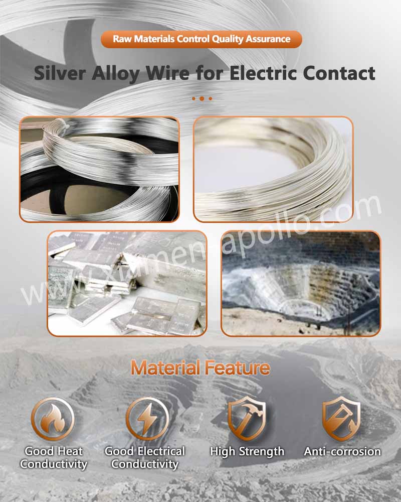
AgNi10 is an electrical contact material containing approximately 90% silver and 10% nickel by nominal composition. Nickel particles dispersed within the silver matrix increase hardness and improve resistance to mechanical deformation compared with solid pure silver.
This material is commonly evaluated for relay contacts where repeated mechanical operation and contact surface durability are important.
AgNi10 Composition and Physical Characteristics
AgNi10 combines the electrical properties of a silver matrix with the strengthening effect of nickel.
The nickel phase restricts plastic deformation and improves the material's resistance to contact surface wear.
Its conductivity is lower than that of high-purity silver because nickel has substantially lower electrical conductivity than silver.
The actual conductivity, hardness and microstructure depend on powder metallurgy, internal oxidation or other material production routes, as well as subsequent processing.
AgNi10 vs. FASg: Electrical and Mechanical Comparison
The following comparison highlights the main differences relevant to micro relay contact selection.
| Comparison Parameter | Solid Pure Silver (FASg) | Silver-Nickel (AgNi10) |
|---|---|---|
| Nominal composition | Ag ≥99.95% for specified high-purity grade | Ag 90% / Ni 10% |
| Electrical conductivity | Approximately 105% IACS at 20°C | Lower than pure silver; grade and process dependent |
| Hardness | Relatively low | Higher than solid pure silver |
| Plastic deformation | More susceptible | Better resistance |
| Mechanical wear resistance | Lower | Generally higher |
| Low-load conduction | Favorable due to high conductivity | Depends more strongly on contact force and surface condition |
| Typical selection priority | Low contact resistance | Mechanical durability and wear resistance |
Why Nickel Improves Contact Mechanical Stability
The nickel phase strengthens the silver matrix and limits localized deformation under repeated mechanical loading.
In a relay contact assembly, this can help maintain contact surface geometry over repeated switching cycles.
Compared with pure silver, AgNi10 is less susceptible to flattening and localized plastic flow under comparable loading conditions.
However, increased hardness does not automatically guarantee lower contact resistance.
A harder contact material may require appropriate contact pressure and surface geometry to establish sufficient real electrical contact area.
This distinction is particularly important for low-current switching, where the contact interface cannot depend on high electrical energy to compensate for inadequate mechanical contact.
AgNi10 Manufacturing and Contact Surface Control
AgNi10 contacts may be manufactured through precision blanking, powder metallurgy-based material production, turning and riveting, depending on the required contact geometry.
For micro relay production, key quality control points include:
- Nickel content and material composition verification.
- Micro-hardness and material consistency.
- Contact diameter and thickness tolerance.
- Surface flatness and burr control.
- Contact resistance testing under specified force.
- Metallographic examination where material structure verification is required.
A controlled contact surface is necessary to prevent dimensional variation and inconsistent electrical contact between production batches.
Consult Our Electrical Engineers Today
Selecting FASg or AgNi10 Based on Relay Contact Force
The correct material selection depends on the relationship between electrical load, mechanical contact force and switching life.
For micro relays operating below 1 A, a material with high electrical conductivity may be preferable when the available contact force is limited. However, when the relay mechanism provides sufficient contact pressure and requires greater resistance to mechanical deformation, AgNi10 may provide a more suitable balance.
Low Contact Force: Prioritize FASg Electrical Conductivity
When the relay design has relatively low closed-contact force, the real contact area may be limited.
Under these conditions, FASg offers an electrical advantage through its higher bulk conductivity and favorable silver surface characteristics.
Typical evaluation scenarios include:
- Smart home control relays switching low-current signals.
- Communication equipment relay interfaces.
- Electronic control circuits with low contact loading.
- Signal switching applications requiring low initial contact resistance.
The actual contact force threshold should be determined through relay testing rather than a universal material-selection rule.
Higher Contact Force: Consider AgNi10 Mechanical Durability
When the relay mechanism provides greater contact force, AgNi10 becomes a practical candidate for applications involving repeated mechanical contact.
Its increased hardness can reduce contact surface deformation and help preserve contact geometry.
This is relevant when the design priority includes:
- Repeated mechanical switching.
- Contact surface wear resistance.
- Reduced plastic deformation.
- Consistent contact geometry over the specified service life.
Nevertheless, AgNi10 must still pass low-level contact resistance testing under the actual operating conditions.
Recommended Material Selection Matrix
| Relay Operating Condition | Recommended Material | Main Engineering Reason |
|---|---|---|
| Below 1 A, low contact force | FASg | Higher conductivity and favorable low-load conduction |
| Below 1 A, moderate contact force | FASg or AgNi10 | Selection depends on resistance and wear requirements |
| Repeated switching with higher mechanical loading | AgNi10 | Greater hardness and resistance to deformation |
| Extremely low allowable contact resistance | FASg | Lower bulk electrical resistance |
| Mechanical wear is the dominant failure mode | AgNi10 | Improved resistance to mechanical surface damage |
Verification Tests Before Mass Production
Material selection should be validated using complete relay assemblies rather than isolated material conductivity data.
Recommended engineering verification includes:
- Initial Contact Resistance: Measure contact resistance using a four-wire Kelvin method under a defined contact force.
- Low-Level Switching Test: Evaluate electrical continuity at the actual operating voltage and current, particularly below 1 A.
- Mechanical Endurance Test: Record contact resistance variation and contact wear throughout the specified switching cycles.
- Environmental Test: Evaluate contact resistance changes under the applicable temperature, humidity and corrosive gas conditions.
- Material Verification: Confirm silver content, nickel content, hardness and material traceability.

Frequently Asked Questions
Q1. Is pure silver or AgNi10 better for micro relays operating below 1 A?
FASg is generally preferred when low contact resistance and high electrical conductivity are the main requirements. AgNi10 is more suitable when mechanical wear resistance and resistance to plastic deformation have greater priority. Final selection requires testing at the actual contact force and switching load.
Q2. How should contact resistance be measured for low-load micro relay contacts?
A four-wire Kelvin measurement is recommended to minimize lead and fixture resistance. Testing should use a defined contact force, specified measurement current and voltage, and controlled surface conditions. Initial resistance and resistance variation after endurance testing should both be recorded.
Q3. What material and quality documents should a micro relay contact supplier provide?
A qualified supplier should provide material composition certificates, batch traceability records, dimensional inspection reports, relevant conductivity and hardness data, and contact resistance test results. RoHS, REACH and ISO 9001 or IATF 16949 documentation should be provided according to the customer's requirements.
contact us
Send your Electrical Silver Solid Contact Rivet for Relays drawings, required material grade, operating current, and closed-contact force for a technical assessment. Obtain a manufacturing feasibility review covering solid silver and AgNi10 contacts, precision stamping, contact riveting, dimensional inspection and production batch traceability. Contact the factory directly to confirm tooling requirements, sample arrangements and mass-production lead times.