Stainless steel stamping quality depends on matching the alloy grade, sheet condition, die clearance, forming force, and lubrication to the component geometry and service environment. For 304 and 316 stainless steel, incorrect tooling clearance or excessive work hardening can cause edge burrs, dimensional drift, galling, and cracking. A controlled process should verify material certificates, establish parameters through die trials, and inspect critical dimensions and surface conditions against the part drawing.
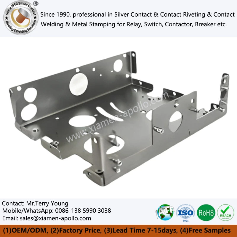
Stainless Steel Grade Selection: 304 vs. 316
Match the Stainless Steel Grade to the Operating Environment
Grade selection should start with corrosion exposure, forming complexity, operating temperature, required strength, and total component cost. A grade that performs well in an indoor electrical enclosure may be unsuitable for chloride-rich or marine environments.
| Selection factor | Type 304 stainless steel | Type 316 stainless steel |
|---|---|---|
| Typical composition | Approximately 18% Cr, 8% Ni | Approximately 16–18% Cr, 10–14% Ni, 2–3% Mo |
| Corrosion behavior | Suitable for many indoor and general industrial environments | Improved resistance to chlorides and many corrosive environments |
| Formability | Good ductility; work hardening must be considered | Good formability; work hardening and tool friction still require control |
| Relative material cost | Usually lower than 316 | Usually higher than 304 |
| Common selection cases | Enclosures, brackets, covers, clips, and general stamped components | Marine-related hardware, chemical-processing components, and chloride-exposed parts |
Verify Hardness, Strength, and Ductility Before Stamping
Stainless steel is supplied in different thicknesses and tempers, and its forming behavior can vary significantly between batches. Incoming inspection should verify the material grade, thickness, surface finish, hardness where specified, and tensile properties where required.
- Sheet thickness: Measure incoming thickness at representative positions and compare it with the drawing and material specification.
- Hardness: Confirm that the measured value falls within the agreed material or temper requirements; excessive hardness can increase forming force and cracking risk.
- Tensile properties: Review yield strength, tensile strength, and elongation when the forming operation is sensitive to springback or localized stretching.
- Surface condition: Identify scratches, pits, roll marks, and protective-film defects before feeding the coil or blank into the die.
For critical parts, record the coil or batch number so that dimensional defects can be traced to the original material lot.
Account for Work Hardening and Springback in 304 Stainless Steel Stamping
Austenitic stainless steels work-harden during plastic deformation. Repeated bending or severe drawing can increase local strength while reducing the remaining ductility available for subsequent forming operations.
Springback also affects flange angles, flatness, and assembled dimensions. Compensation should be based on measured trial parts rather than a fixed allowance applied to every geometry. For repeat production, monitor incoming material variation, bend radius, forming sequence, and tool wear.
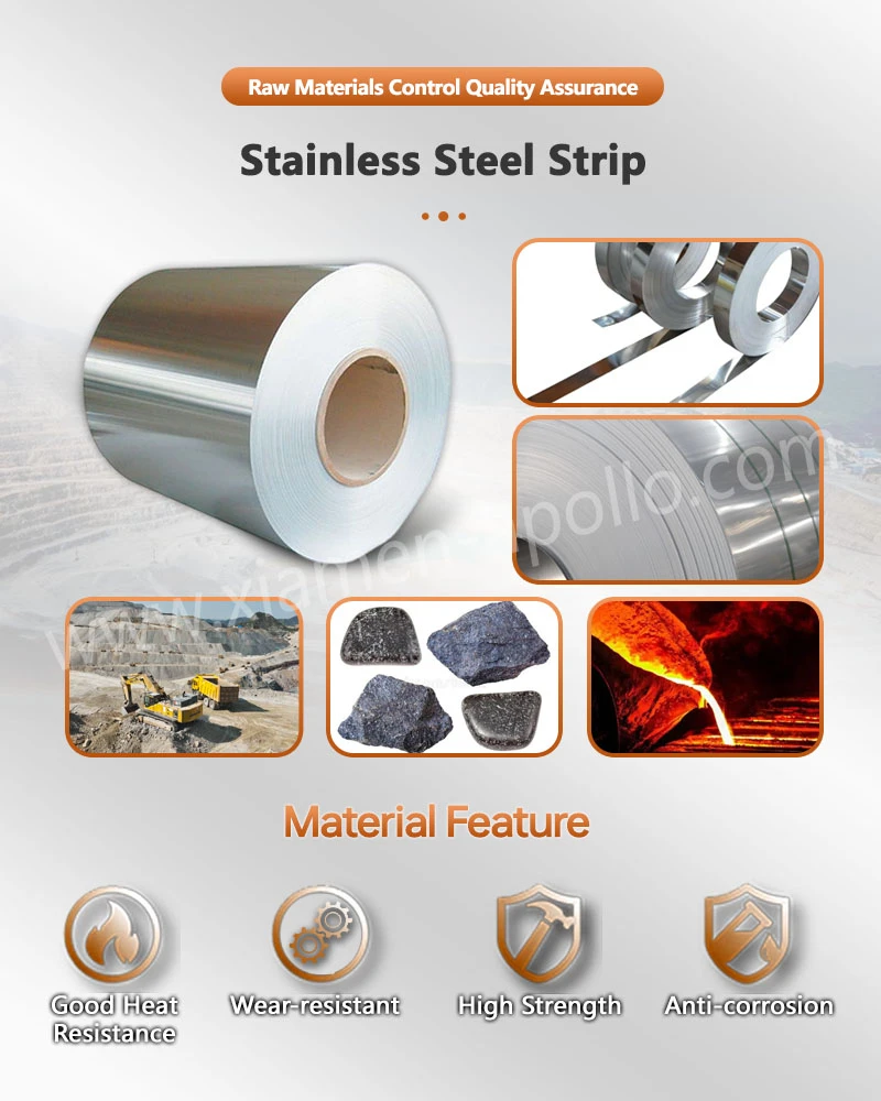
Stainless Steel Stamping Die Design: Clearance, Tool Steel, and Surface Treatment
Establish Die Clearance from Thickness and Operation Type
Die clearance directly affects cutting force, burr formation, edge quality, and tool life. A preliminary clearance of approximately 5%–10% of sheet thickness per side may be used as a starting point for some conventional blanking operations, but it is not a universal setting for stainless steel.
The correct value depends on grade, thickness, tensile properties, blanking geometry, required edge quality, and the tooling supplier's process data. Confirm the clearance through trial stamping and section or burr inspection.
| Die-design variable | Initial engineering consideration | Verification method |
|---|---|---|
| Cutting clearance | Trial approximately 5%–10% of sheet thickness per side where appropriate | Measure burr height, edge profile, and cutting quality |
| Punch and die alignment | Minimize eccentric loading and uneven clearance | Check alignment and inspect wear patterns |
| Punch edge condition | Maintain suitable cutting-edge sharpness | Inspect edge chipping, wear, and burr growth |
| Forming radius | Match the material's ductility and required geometry | Inspect cracks, thinning, and springback |
| Die surface finish | Reduce friction and material pickup | Check galling, scratches, and transferred metal |
The clearance figure is a starting range, not a guaranteed production specification. For demanding parts, define the approved value in the process documentation after testing.
Select Wear-Resistant Tool Steel and Suitable Surface Treatments
Progressive dies and compound dies used for stainless steel stamping must withstand repeated loading, friction, and abrasive wear. Tool steel selection should consider production volume, cutting geometry, impact loading, and maintenance requirements.
Depending on the application, suitable tool steels may include D2-type cold-work steel or other grades selected by the tooling engineer. Surface treatments such as nitriding or hard-chromium plating may be considered when compatible with the tool material, geometry, and operating conditions.
The treatment should not be selected on hardness alone. Evaluate coating adhesion, surface finish, dimensional effects, galling resistance, and maintenance requirements. A poorly selected coating or damaged surface can accelerate stainless steel pickup and leave marks on stamped parts.
Use Progressive Stamping for Complex Geometry
Complex stainless steel components may require multiple stations for piercing, notching, bending, embossing, forming, and final cutoff. Progressive die stamping can improve repeatability and production throughput when strip layout, station sequence, and part transfer are properly engineered.
- Piercing and blanking: Separate cutting operations from severe forming where the design allows.
- Bending: Control bend radius and orientation relative to the material rolling direction where relevant.
- Drawing and embossing: Monitor local thinning, material flow, and wrinkling.
- Final sizing: Use a dedicated sizing or restrike station when dimensional control cannot be achieved consistently in the preceding stations.
Download Contact Material Spec Sheet
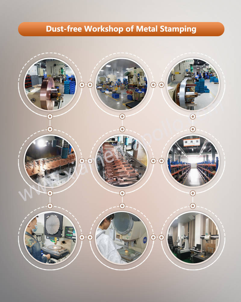
Stainless Steel Stamping Parameters: Speed, Force, and Lubrication
Set Stamping Speed According to Material and Die Conditions
There is no single stamping speed suitable for every 304 or 316 component. The correct operating speed depends on sheet thickness, part geometry, die rigidity, press type, lubrication, and the time available for material flow.
Excessive speed can increase heat generation, vibration, lubricant breakdown, and the severity of material pickup. An unnecessarily low speed can also affect throughput and may change the behavior of some forming operations. Establish a validated operating window during die trials.
During commissioning, record the press speed, feed pitch, material thickness, lubrication method, and observed defect rate. Increase speed in controlled steps while monitoring burr height, cracks, dimensional variation, surface scoring, and abnormal noise or vibration.
Determine Press Force Through Engineering Calculations and Die Trials
Insufficient force may result in incomplete forming or inconsistent feature height. Excessive force can overload the press or tooling, accelerate wear, and damage the workpiece.
For blanking, a first-order estimate of cutting force is:
Cutting force ≈ total cutting perimeter × sheet thickness × material shear strength
The result must be adjusted for the actual tooling configuration and operating conditions. Press selection must also account for the force profile over the stroke, available energy, off-center loading, stripping force, and the load capacity of the die and press.
For drawing and complex forming, the blanking equation alone is insufficient. Use process-specific calculations, material data, and physical die trials to establish the required force and operating window.
Control Lubrication to Reduce Galling and Surface Damage
Stainless steel can adhere to tooling under high contact pressure, especially during sliding and drawing operations. This material pickup, commonly called galling, can create scratches, rough surfaces, dimensional changes, and premature tool wear.
| Lubrication consideration | Process objective | Control method |
|---|---|---|
| Lubricant type | Support cutting, bending, or drawing without damaging the part | Select for the operation, material, and downstream cleaning process |
| Application quantity | Maintain a consistent lubricating film | Control spray, roller, or metered application |
| Lubricant distribution | Prevent dry contact and localized buildup | Inspect difficult-to-reach forming areas |
| Residue removal | Avoid contamination of welding, coating, or assembly | Validate the cleaning process against downstream requirements |
| Tool cleanliness | Reduce metal pickup and transferred scratches | Establish inspection and cleaning intervals |
For components that will be welded, plated, bonded, or assembled into electrical equipment, confirm lubricant compatibility with the downstream process. Residue limits should be specified where contamination can affect adhesion, contact interfaces, or coating quality.
Distinguish Cutting Defects from Forming Defects
Different defect mechanisms require different corrective actions. Increasing press force will not resolve every defect, and excessive force can make the problem worse.
| Defect | Likely causes | Corrective checks |
|---|---|---|
| Excessive burrs | Worn cutting edges, unsuitable clearance, misalignment | Inspect punch edges, clearance, and die alignment |
| Edge cracking | Excessive deformation, unsuitable bend radius, material variation | Review material condition, forming radius, and forming sequence |
| Galling or scoring | Tool pickup, inadequate lubrication, damaged surface finish | Clean and inspect tooling; review lubricant coverage |
| Springback | Material strength variation, geometry, forming sequence | Measure material properties and adjust forming compensation |
| Wrinkling | Uncontrolled material flow or unsuitable blank-holder conditions | Review blank geometry, restraint, and drawing conditions |
| Dimensional drift | Tool wear, feed variation, material variation, press instability | Analyze dimensional trends by batch and station |
Stainless Steel Stamping Quality Control: Dimensions, Surfaces, and Traceability
Define Critical-to-Quality Dimensions Before Production
Dimensional inspection should be based on the drawing's tolerances and functional requirements, not on a generic claim of precision. Identify critical-to-quality (CTQ) features such as hole position, flange height, bend angle, flatness, and assembly interfaces.
Use suitable measuring instruments for each feature:
- Calipers and micrometers for accessible linear dimensions and thickness.
- Pin gauges or dedicated gauges for hole and slot dimensions.
- Optical measurement systems or coordinate measuring machines (CMMs) for complex profiles and positional relationships.
- Dedicated fixtures for repeatable checks of formed geometry and assembly fit.
For tight-tolerance parts, evaluate measurement-system capability and repeatability before relying on inspection data. If a dimension drifts systematically, assess tool wear, feed alignment, material thickness, and press stability before changing the nominal tool geometry.
Inspect Burr Height, Cracks, and Surface Finish
Surface acceptance criteria should define the permitted level of scratches, dents, burrs, discoloration, and other visible defects. These criteria must reflect the part's function, installation position, and subsequent processing.
Parts intended for electrical assemblies may require particular attention to edge conditions, burr direction, cleanliness, and contact with adjacent components. Where sharp edges can damage insulation or create assembly risks, specify a measurable burr limit and the inspection method.
Visual inspection can identify many surface defects, but suspected cracks may require magnification or an appropriate non-destructive testing method. Select the method according to material thickness, defect type, and the acceptance standard.
Verify Mechanical Properties and Material Traceability
For safety-related or function-critical parts, inspection records should connect the finished components to the incoming material lot and the approved process revision.
- Retain material certificates and incoming inspection records where required by the purchase specification.
- Record tool maintenance, press settings, and process changes.
- Use first-article inspection to verify new tooling or engineering changes.
- Define sampling frequency and reaction plans for critical dimensions.
- Apply lot identification and nonconforming-product controls to prevent unintended release.
ISO 9001 and IATF 16949 are quality management system standards, not guarantees that every part meets a specific dimensional or mechanical requirement. Confirm certification scope and customer-specific requirements before making compliance claims.
Apply Relevant Standards Without Confusing Their Scope
Standards should be selected according to the actual product, material, and customer specification. ASTM A240/A240M is commonly used for chromium and chromium-nickel stainless steel plate, sheet, and strip for pressure vessels and general applications; the applicable edition and product form must be confirmed. Other material and test standards may apply to the specified grade, thickness, and mechanical properties.
| Requirement | Reference or method | Application note |
|---|---|---|
| Stainless steel sheet specification | ASTM A240/A240M, where applicable | Confirm grade, product form, and edition |
| Quality management | ISO 9001 | Verify the certified organization's scope |
| Automotive quality management | IATF 16949, where applicable | Confirm applicability to the supplying site and customer requirements |
| Chemical restrictions | RoHS and REACH, where applicable | Check the relevant product category and declaration requirements |
| Corrosion testing | ASTM B117, where specified | Salt-spray exposure does not automatically predict service life |
| Dimensional acceptance | Customer drawing and inspection plan | Define tolerance, sampling, and measurement method |
Do not apply ASTM B117 automatically to every stainless steel stamped part. Salt-spray testing should be specified only when relevant to the product, surface condition, coating, or customer validation plan.

Stainless Steel Stamping Factory Safety and Equipment Maintenance
Control Press and Die Hazards During Production
Mechanical and hydraulic presses present pinch, crush, and ejection hazards. Safety controls must be based on a documented risk assessment, applicable regulations, and the specific press and die configuration.
- Train operators in the approved setup, feeding, and shutdown procedures.
- Use suitable guarding, interlocks, and presence-sensing devices where required by the risk assessment and machine design.
- Wear task-appropriate personal protective equipment, including eye protection and suitable handling gloves where safe for the operation.
- Use approved tools for handling sharp blanks and finished parts.
- Never reach into the die area while the machine is cycling.
Gloves must not be used near exposed rotating or moving equipment when they create an entanglement hazard. PPE does not replace guarding, interlocks, or safe operating procedures.
Isolate Energy Before Adjustment or Maintenance
Operators must not adjust, clear, or repair tooling while the press is running or capable of unexpected movement. Before maintenance, apply the site's energy-isolation procedure, including lockout/tagout where required, and verify that stored mechanical, hydraulic, pneumatic, and electrical energy has been controlled.
Routine maintenance should cover press brakes and guides, die fasteners, lubrication systems, sensors, guards, and emergency-stop functions as applicable. Record abnormal vibration, noise, temperature, and recurring defects so that maintenance can be scheduled before they cause a safety incident or production interruption.
Consult Our Electrical Engineers Today
Production Readiness Checklist for Custom Stainless Steel Stamping
Before approving a new part or moving into mass production, confirm the following items:
- Material: Grade, thickness, temper, certificate, and lot traceability meet the approved specification.
- Tooling: Die clearance, alignment, cutting-edge condition, forming radii, and surface treatment are verified.
- Process: Press speed, force, feed pitch, and lubricant application have been established through documented trials.
- Quality: CTQ dimensions, burr limits, surface acceptance criteria, sampling frequency, and reaction plans are defined.
- Validation: First-article results and any required mechanical, corrosion, or downstream-process tests are accepted.
- Production control: Tool maintenance, operator training, nonconforming-product handling, and revision control are in place.
Stainless steel stamping performance is determined by the interaction of material properties, die design, press settings, lubrication, inspection, and operator safety. Treating these factors as one controlled manufacturing system helps reduce scrap, stabilize dimensions, and maintain repeatable output across production batches.
Frequently Asked Questions
1. How should die clearance be selected for 304 stainless steel stamping?
A preliminary clearance of approximately 5%–10% of sheet thickness per side may be considered for certain blanking operations. The approved value must be established through die trials and verified by burr height, edge quality, material thickness, and tool-life results.
2. What information is required to request a quotation for custom stainless steel stamping?
Provide the 2D drawing or 3D CAD file, stainless steel grade, sheet thickness, annual or batch quantity, dimensional tolerances, surface requirements, and any applicable compliance or inspection requirements. These details allow the factory to review tooling, process feasibility, and production cost.
3. How can buyers verify material traceability and quality-system compliance?
Request the applicable material certificate, batch identification, inspection records, and evidence of relevant quality-system certification. Confirm that the certificate covers the actual manufacturing site and that the agreed inspection plan addresses the part's critical dimensions and acceptance criteria.
contact us
Need a production-ready solution for your next stainless steel stamping project? Submit your drawings and material requirements now for a factory-level tooling and process review, covering feasibility, quality controls, and production planning.