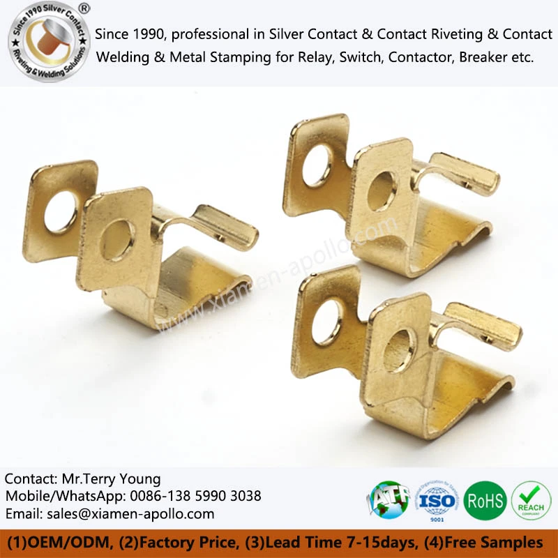
A Multi-Bend Brass Stamping Terminal is an electrical connection component formed from a brass strip through progressive stamping, piercing, blanking, and multiple bending operations. Its primary manufacturing challenge is not simply the number of bends, but the control of material deformation, springback, bending sequence, and final assembly position. In relays, low-voltage electrical equipment, circuit breakers, and automotive electrical assemblies, the brass grade, strip condition, bending sequence, and die structure directly affect electrical continuity, mechanical retention, and dimensional consistency.
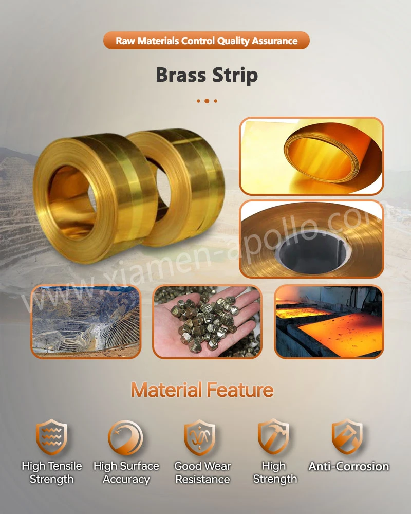
H62, H65, and H68 are commonly used brass grades with different combinations of strength, ductility, and forming characteristics. Therefore, material selection for a Metal Brass Terminal Contact should be determined together with the number of bends, bending angle, terminal cross-section, and assembly load rather than based on material cost alone.
Why Multi-Bend Structures Are Used for Precision Brass Stamping Parts
Conventional flat stamped terminals mainly use a planar section for electrical connection or mechanical attachment. A Electrical Brass Terminal Contact Accessories can form a three-dimensional structure through successive bending operations, allowing one stamped component to perform electrical conduction, positioning, retention, and mechanical support functions.
For relay and low-voltage electrical assemblies, multiple bends can reduce the number of individual components. For example, a structure that would otherwise require separate connection, positioning, and support parts can be produced from one brass strip through piercing, blanking, and multiple bending operations within a progressive die.
Typical applications include:
- Relay terminals and internal connectors
- Low-voltage electrical terminals
- Circuit breaker connection components
- Smart meter terminal assemblies
- Automotive electrical connectors
- EV auxiliary electrical assemblies
- Control panels and industrial electrical equipment
However, increasing the number of bends also increases the importance of material springback, die clearance, and feed stability. Multi-bend forming is therefore not simply a matter of adding more bending operations. It requires coordinated control of material properties, die design, forming sequence, and assembly datums.
Forming Characteristics of H62, H65, and H68 Brass
Brass stamping terminals must normally satisfy both electrical conductivity and forming requirements. H62, H65, and H68 are commonly specified brass grades, but they should not automatically be processed under identical stamping conditions.
H62 Brass
H62 is a commonly used brass grade with balanced physical and processing characteristics. It provides good cold-forming capability together with suitable machinability, brazing, and welding characteristics.
For a Stamped Brass Bracket involving piercing, blanking, and multiple bending operations, H62 can be considered where forming capability and electrical connection requirements need to be balanced.
H65 Brass
H65 sits between H62 and H68 in terms of material characteristics. It provides a different balance between strength, ductility, and material cost.
For terminals with multiple bends and defined mechanical stiffness requirements, the actual bending radius, material thickness, and assembly load should be evaluated before final material selection.
H68 Brass
H68 provides good ductility together with relatively high strength and can be considered for brass components requiring both forming capability and mechanical strength.
For complex multi-bend structures, engineering validation should focus on potential cracking at bending zones and dimensional changes caused by springback after forming.
There is therefore no universal brass grade that applies to every Cold Stamped Brass Component. Procurement and engineering teams should define the material grade together with material thickness, bending direction, number of bends, and final assembly requirements.
Typical Manufacturing Process of Socket Brass Contact Bracket
A typical brass multi-bend terminal production sequence can be arranged as:
Brass strip → Feeding → Piercing → Blank forming → Local forming → Multiple bending → Cut-off → Dimensional inspection → Surface treatment or subsequent assembly
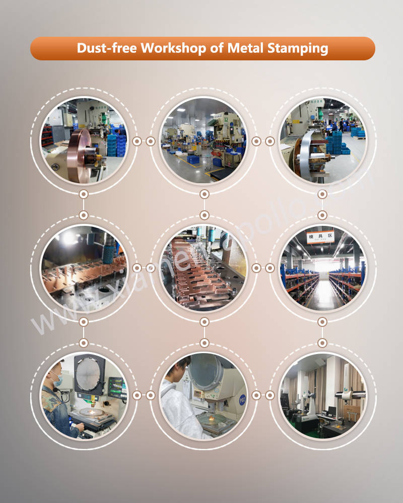
Progressive stamping is suitable for products with stable geometry and recurring production demand. Piercing and blanking normally establish the basic profile and positioning features, followed by forming stations that gradually create the three-dimensional terminal structure.
For a Switch Brass Stamping Contact, the bending sequence is particularly important. Once a previous bending operation creates a high three-dimensional section, subsequent stamping stations may experience tool interference or restricted forming space. Die design therefore needs to account for feed direction, forming height, punch movement, strip progression, and part ejection before production begins.
Piercing and Positioning
Mounting holes, rivet holes, and positioning holes are generally produced before bending because the flat strip condition provides more stable feeding and punching.
Hole positions also serve as important inspection datums for subsequent dimensional control. For terminals assembled with relay housings, plastic components, or other metal parts, hole position and edge distance should be defined according to the actual assembly reference points.
Multiple-Bend Forming
Multiple bending is the main manufacturing feature that distinguishes this type of terminal from a conventional flat stamped component.
Key forming factors include:
- Material thickness
- Bending direction
- Bend radius
- Springback
- Distance between bends
- Tool clearance
- Forming sequence
Brass undergoes elastic recovery after plastic deformation, so the actual formed angle may differ from the theoretical die angle. For terminals that must fit accurately into plastic housings or maintain a defined spacing from adjacent components, the final forming parameters should be established through die compensation and first-article validation.
How Stamping Dies Affect Terminal Consistency
The dimensional consistency of a Switch Brass Stamping Contact depends not only on the stamping press, but also on die positioning, strip feeding accuracy, and cumulative dimensional variation between forming stations.
In progressive stamping, the strip passes through multiple stations in sequence. If positional variation occurs at an early operation, that variation can carry forward into subsequent stations and eventually appear as hole misalignment, inconsistent bend height, or deviation in the overall terminal position.
Engineering validation should therefore address the following parameters:
| Inspection Item | Engineering Focus |
|---|---|
| Material grade | H62 / H65 / H68 or specified grade |
| Material thickness | Match die clearance and bending requirements |
| Hole position | Maintain assembly datum accuracy |
| Bend angle | Evaluate actual angle after springback |
| Bend height | Confirm spatial assembly dimensions |
| Terminal width | Verify insertion and mounting clearance |
| Surface condition | Check burrs, scratches, and stamping marks |
| Assembly fit | Verify actual component compatibility |
Actual dimensional tolerances should be defined according to the product drawing and customer technical specification rather than replaced by a generic tolerance range.
Quality Control Priorities for Metal Brass Terminal Contact
For procurement and QA teams, inspection should not be limited to visual appearance. Terminal function depends on the combined condition of material, dimensions, and forming geometry.
The incoming material should first be verified against the specified grade and thickness. Hole dimensions, terminal width, bend height, and key assembly dimensions should then be inspected according to the control plan.
For parts with several sequential bends, the overall terminal geometry also requires attention. Individual bend dimensions may fall within specification while the completed component still fails to fit correctly because of accumulated dimensional variation.
Stamping burrs are another important inspection item. Excessive burrs can interfere with insertion, assembly, or adjacent insulation components. Punch-to-die clearance, die edge condition, and material thickness therefore need to remain properly matched throughout production.
If the terminal requires plating, surface treatment should be included in the overall quality-control process. Final assembly dimensions should be evaluated together with the effects of the selected plating process rather than treating stamping and surface treatment as completely independent operations.

contact us
If you are sourcing Multi-Bend Brass Stamping Terminal components and already have 2D/3D drawings, material specifications, or annual volume requirements, submit the engineering data for immediate DFM review, tooling assessment, and quotation from a factory equipped for progressive stamping, precision bending, die development, and volume production.